
Page 392 - MISUMI Thailand Economy Series
P. 392
Format Series Price Ratio Shipping Search Drawing Product Material Table Techinfo Others BD M D GM Format Series Price Ratio Shipping Search Drawing Product Material Table Techinfo Others BD M D GM
Name Date KW Pict Title Name Date KW Pict Title
AK AK
M M
Economy Series Product Overview Product Overview Economy Series
Ball Splines Ball Splines
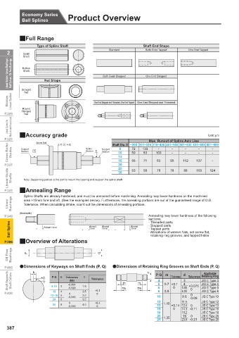
QFull Range
Type of Spline Shaft Shaft End Shape
2 Solid Standard Both Ends Tapped One End Tapped 2
Shaft
Linear Guides / Linear Bushings / Ball Splines / Oil Free Bushings Hollow Nut Shape Both Ends Stepped One End Stepped Ball Splines / Oil Free Bushings Linear Guides / Linear Bushings /
Shaft
Straight
Nut
Miniature Linear Guides One End Stepped and Threaded, One End Tapped One End Stepped and Threaded Linear Guides Miniature
Round
Flanged
P.309 Nut P.309
Linear Guides for Medium and Heavy Load Medium and Heavy Load Linear Guides for
Unit: μm
P.321 QAccuracy grade A-B Shaft Dia. D ~200 201~315 316~400 401~500 501~630 631~800 801~900 P.321
Max. Runout of Spline Axis Line
Spline Nut
Cross Roller Guides Support A Spline B Support 10 72 133 103 - - - - - - - - Guides Cross Roller
G
8
-
Section
Section
Section
83
59
13
-
20
P.337 16 56 71 83 95 112 137 124 P.337
25
Linear Guide Shafts Note: Supporting portion is the part to mount the bearing and support the spline shaft. Shafts Linear Guide
70
88
103
78
58
53
30
P.341 QAnnealing Range P.341
Spline Shafts are already hardened, and must be annealed before machining. Annealing may lower hardness on the machined
Linear Bushings area +15mm fore and aft. (See the examples below). Furthermore, the annealing portions are out of the guaranteed range of O.D. Bushings Linear
Tolerance. When calculating stroke, count out the dimensions of annealing portions.
(Example)
P.349 Annealing may lower hardness of the following P.349
sections:
· Threaded parts
Ball Spline About 15mmAbout 15mm About About 15mm About About · Stepped parts Ball Spline
About About
· Tapped parts
15mm
15mm
15mm
15mm
15mm
· Alterations of wrench flats, set screw flat,
retaining ring grooves, and tapped holes
P.386 QOverview of Alterations P.386
Oil Free Bushings P Q Bushings Oil Free
P.409 IDimensions of Keyways on Shaft Ends (P, Q) IDimensions of Retaining Ring Grooves on Shaft Ends (P, Q) P.409
Shaft Supports Shaft Collars t P·Q b Tolerance t Tolerance m m P·Q 0.7 Tolerance d 3 4 Tolerance Retaining Ring Shaft Collars Shaft Supports
b
Applicable
d
m
JIS E Type 3
4
(N9)
5
JIS E Type 4
+0.1
-0.004
+0.075
6.05
JIS E Type 6
12
2.5
P.430 8·10 3 4 -0.029 1.8 +0.1 TA TB 6 8 0.9 0 5.05 0 JIS E Type 5 P.430
0
0
13~16 5 -0.030 3.0 10 9.6 0 JIS C Type 10
20 6 3.5 -0.09
0 +0.2 12 11.5 JIS C Type 12
25 8 4.0 13 1.15 +0.14 12.4 0 JIS C Type 13
-0.036 0
15 0 14.3 -0.11 JIS C Type 15
16 15.2 JIS C Type 16
20 19 0 JIS C Type 20
25 1.35 23.9 -0.21 JIS C Type 25
387
1BSU @&/ JOEC
1BSU @&/ JOEC