
Page 79 - MISUMI Thailand Economy Series
P. 79
Format Series Price Ratio Shipping Search Drawing Product Material Table Techinfo Others BD M D GM Format Series Price Ratio Shipping Search Drawing Product Material Table Techinfo Others BD M D GM
Title
KW
KW
Pict
Pict
Title
Date
Name
Name
Date
AK AK
M M
1 1
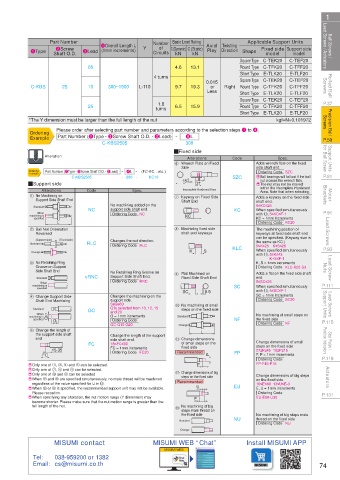
Ball Screws / Lead Screws / Actuators 1Type Part Number 3Lead 4Overall Length L Y Number C (Dynamic) C (Static) Axial Twisting Square Type C-TEK20 C-TEF20 Lead Screws / Actuators Ball Screws /
Basic Load Rating
Applicable Support Units
of
2Screw
Fixed side Support side
(1mm increments)
Play Direction Shape
Circuits
model
kN
model
Shaft O.D.
kN
E-TLF20
E-TLK20
Short Type
Rolled Ball Screws C-KBS 25 05 300~1500 L-110 4 turns 4.6 13.1 0.015 Right Round Type C-TFK20 C-TFF20 Screws Rolled Ball
C-TEF20
Square Type C-TEK20
Round Type C-TFK20
or
19.3
9.7
C-TFF20
10
Less
Short Type
E-TLK20
E-TLF20
P.37 25 turns 6.5 15.9 Square Type C-TEK20 C-TEF20 P.37
1.8
Round Type C-TFK20
C-TFF20
Precision Ball Screws *The Y dimension must be larger than the full length of the nut kgf=N×0.101972 Screws Precision Ball
E-TLK20
E-TLF20
Short Type
Please order after selecting part number and parameters according to the selection steps 1 to 4.
4L
Example
P.59 Ordering Part Number (1Type · 2Screw Shaft O.D. · 3Lead) - - 300 P.59
C-KBS2505
Support Units for Ball Screw Alteration QFixed side Code Adds wrench flats on the fixed for Ball Screw Support Units
Alterations
Spec.
Wrench Flats on Fixed
6
Ordering Code SZC
Example
P.81 Ordering Part Number (1Type · 2Screw Shaft O.D. · 3Lead) - 4L - (FC·KC…etc.) Side 0 10 7 SZC side shaft end. P.81
C-KBS2505
- 680 -
KC10
E Ball bearings will fall out if the ball
nut crosses the wrench flats.
QSupport side 18 -0.25 37 E The nut may not be moved
within the Incomplete Hardened
Motor Brackets 1 No Machining on Code Spec. 7 Incomplete Hardened Area Adds a keyway on the fixed side Brackets Motor
Alterations
Area. Note that when selecting.
Keyway on Fixed Side
Support Side Shaft End
5≤KC≤26
Standard No machining added on the Shaft End shaft end.
support side shaft end.
P.91 When NC Ordering Code NC KC When specified simultaneously P.91
with Q, 5≤KC≤F-1
machining is L KC KC = 1mm increments
specified
Lead Screws 2 Ball Nut Orientation 8 Machining fixed side The machining position of Lead Screws
Ordering Code KC20
shaft end keyways
Reversed
keyways at fixed side shaft end
can be specified. (Keyway size is
(Fixed side)
(Support side)
Ordering Code RLC
5≤K≤25 K+S≤26
P.93 Standard RLC Changes the nut direction. KLC the same as KC.) P.93
When specified simultaneously
Change K S with Q, 5≤K≤43
Lead Screw Nuts 3 No Retaining Ring No Retaining Ring Groove on 9 Flat Machined on K, S = 1mm increments Nuts Lead Screw
K+S≤F-1
Groove on Support
Ordering Code KLC-K20-S3
Side Shaft End
Adds a flat on the fixed side shaft
Support Side Shaft End.
Standard
5≤SC≤26
When
P.111 machining is vRNC Ordering Code RNC Fixed Side Shaft End SC end. P.111
When specified simultaneously
specified
with Q, 5≤SC≤F-1
SC
0.5
Lead Screws Support Units 4 Standard GC Changes the machining on the 0 No machining of small SC = 1mm increments Support Units Lead Screws
Change Support Side
Ordering Code SC20
support side.
Shaft End Machining
5≤G≤60
Q is selected from 10, 12, 15
steps on the fixed side
and 20
When
the fixed side
Ordering Code
specified
P.115 machining is Qh7 G G = 1mm increments Standard NF No machining of small steps on P.115
Ordering Code NF
GC-Q10-G20
Change
Change the length of
5
L
Stop Plates / Position Indicators the support side shaft FC Change the length of the support Q Change dimensions Change dimensions of small Position Indicators Stop Plates /
end
side shaft end.
of small steps on the
18≤FC≤60
steps on the fixed side
fixed side
FC = 1mm increments
F, P = 1mm increments
P.119 FC 15.35 Ordering Code FC20 Recommended P FP 27≤F≤45 10≤P≤15 P.119
Ordering Code
E Only one of 1, 3, 4 and 5 can be selected. F FP-F45-P15
Actuators E Only one of 0 and Q can be selected. W Recommended Change dimensions of big steps Actuators
E Only one of 7, 8 and 9 can be selected.
Change dimensions of big
steps on the fixed side
E When W and e are specified simultaneously, no male thread will be machined
on the fixed side
regardless of the value specified for U in W.
16≤E≤80 13≤U≤E-3
Please reconfirm.
Ordering Code
P.131 E When W or e is specified, the recommended support unit may not be available. U EU E, U = 1mm increments P.131
E When specifying any alteration, the nut motion range (Y dimension) may
EU-E80-U30
become shorter. Please make sure that the nut motion range is greater than the E
full length of the nut. No machining of big
e steps male thread on
the fixed side No machining of big steps male
Standard NU thread on the fixed side
Ordering Code NU
Change
MISUMI contact MISUMI WEB “Chat” Install MISUMI APP
MISUMI WEB
Tel: 038-959200 or 1382
Email: cs@misumi.co.th 74
110310542249
1BSU @&/ JOEC
1BSU @&/ JOEC