
Page 961 - MISUMI Thailand Economy Series
P. 961
Format Series Price Ratio Shipping Search Drawing Product Material Table Techinfo Others BD M D GM Format Series Price Ratio Shipping Search Drawing Product Material Table Techinfo Others BD M D GM
KW
Pict
KW
Pict
Title
Title
Date
Date
Name
Name
AK AK
M M
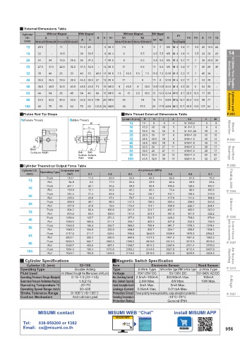
Q External Dimensions Table
Cylinder Without Magnet With Magnet Without Magnet With Magnet P1
I.D. A C D E K1 N1 N2 O P2 P3 S T1 T2
(mm) Stroke≤50 Stroke≥60 Stroke≤50 Stroke≥60 A C Stroke=5 Stroke>5 Stroke=5 Stroke>5 N1 N2 Thread Through Hole
12 20.5 - 17 - 31.5 28 - 6 M 3 7.5 5 9 7 M5 M 4 3.4 11 3.5 25 15.5 22
14 16 22 34 - 18.5 29.5 34 30.5 - - 8 M 4 8 9 5.5 9.5 5.5 M5 M 4 3.4 11 3.5 29 20 28 14
-
Air Cylinders / Valves / Regulators / Shock Absorbers / O-Rings 25 27.5 37.5 22.5 32.5 37.5 32.5 49.5 13 M 8 7.5 11 10.5 6.5 5.5 10.5 11 5.5 G1/8 M 6 5.2 17 7 7 7 8 40 28 40 - - - Shock Absorbers / O-Rings Air Cylinders / Valves / Regulators /
20
36
9.5 5.5
31.5
5.5
7 M 5
5.2 17
24
M 6
19.5
M5
7
36 25.5 36
M5
12 M 6
-
M 6
32
40
40
10.5 7.5 G1/8 M 6
33
7.5
33
5.2 17
30
45 34
23
40
53 40
11
39.5
57
29.5
36.5
13 M 8
11
46.5
46.5 39.5
8
5.2 17
8
50
30.5
48.5
10.5 10.5 G1/4 M 8
40.5
15 M10
6.5 22
64 50
9
71
10.5
9
48.5 40.5
38.5
63
Cylinders and Accessories 100 44 54 36 46 54 46 123.5 26 M20 14 16 15 9.5 17.5 10.5 15 10.5 G1/4 M10 8.7 28.5 10.5 77 60 - - - Accessories Cylinders and
84
15 M10
80
53.5
63.5 53.5 104
14
16
20 M16
14
53.5
43.5
98 77
G3/8 M12 10.7 35.5 13.5
63.5
63
20
75
75
20
53
63
65
17.5 G3/8 M12 10.7 35.5 13.5 117 94
P.951 QPiston Rod Tip Shape B(Male Thread) QMale Thread External Dimensions Table K2 V W P.951
B
Cylinder I.D. (mm)
J
I
H
N(Female Thread)
Shock Absorber H J B 12 14 10 9 10 8 4 5 6 M 5×0.8 10 6 8 5 6 8 Absorber Shock
16
M 6×1.0
15.5
20
12
18.5
12
M 8×1.25
32
M14×1.5
16
14
28.5
19
20.5
P.991 φV φV K2 25 22.5 15 17 6 8 M10×1.25 12 10 P.991
40 28.5 20.5 19 11 8 M14×1.5 16 14
50
17
27
W
20
M18×1.5
33.5
26
Rod End Bearings Both Both I Both 100 33.5 26 27 11 M18×1.5 20 17 Bearings Rod End
W
63
Surfaces Width
80
32.5
22
M22×1.5
25
13
32
43.5
Surfaces
Surfaces
Width
Width
43.5
27
32
32.5
36
13
M26×1.5
P.999 QCylinder Theoretical Output Force Table Air pressure (MPa) P.999
Compression area
Cylinder I.D.
Floating Joint (mm) Operating Type (mm 2 ) 0.1 8.5 0.2 0.3 0.4 0.5 0.6 0.7 Floating Joint
67.9
45.2
56.5
33.9
79.2
Push
11.3
22.6
113.1
12
Pull
17.0
25.4
50.9
33.9
84.8
42.4
59.4
90.5
150.8
75.4
Pull
60.3
15.1
30.2
45.2
105.6
P.1004 16 Push 201.1 20.1 40.2 60.3 80.4 100.5 120.6 140.7 P.1004
20 Push 314.2 31.4 62.8 94.2 125.7 157.1 188.5 219.9
23.6
141.4
164.9
Pull
94.2
70.7
47.1
117.8
235.6
Silencer 25 Push 490.9 49.1 98.2 147.3 196.3 245.4 294.5 343.6 Silencer
151.1
264.4
75.6
113.3
188.9
37.8
377.8
226.7
Pull
32 Push 804.2 80.4 160.8 241.3 321.7 402.1 482.5 563.0
301.6
603.2
422.2
Pull
181.0
361.9
241.3
60.3
120.6
P.1006 Material: Cylinder Block Material Aluminum Alloy 40 Push 1256.6 125.7 251.3 377.0 502.7 628.3 754.0 879.6 P.1006
Pull
1055.6
211.1
633.3
738.9
316.7
105.6
527.8
422.2
Control Valves and Accessories Surface Treatment: Clear Anodized 50 Push 1963.5 196.3 392.7 589.0 1246.9 1558.6 1178.1 1374.4 and Accessories Control Valves
785.4
981.7
Pull
1154.5
824.7
989.6
329.9
164.9
494.8
659.7
1649.3
935.2
623.4
311.7
1870.3
Push
3117.2
2182.1
63
Pull
560.6
840.9
3015.9
2010.6
502.7
3518.6
2513.3
5026.5
P.1007 80 Push 2803.1 280.3 1005.3 1508.0 1121.2 1401.5 1681.9 1962.2 P.1007
453.6
3175.0
1360.7
2721.4
907.1
4535.7
2267.8
Pull
1814.3
Air Source Handling Q Cylinder Specifications 705.0 1409.9 QMagnetic Switch Specification 4229.8 4934.8 Handling Air Source
4712.4
2356.2
1570.8
3927.0
7854.0
5497.8
785.4
Push
3141.6
100
3524.9
2819.9
2114.9
7049.7
Pull
Cylinder I.D. (mm)
Electronic Sensor
12~100
P.1015 Operating Type Double Acting Item 2-Wire Type NPN 3-Wire Type PNP 3-Wire Type Reed Sensor P.1015
Type
2-Wire Type
Fluid Used Air (filtered through the filter screen of 40 μm) Voltage 10V~28V DC 30/200mA Max. 5V~240V AC/DC
5V~30V DC
Operating Pressure Range Mpa(psi)
0.15~1.0 (22~145)
Max. Switching Current 2.5mA~100mA
100mA
O-Rings Guaranteed Pressure Resistance Mpa(psi) 1.5(215) Max. Contact Capacity 2.8W Max. 5mA Max. 10W Max. O-Rings
6W Max.
3mA Max.
-
Internal Consumption Current
Operating Temperature °C
-20~70
Operating Speed Range mm/s 30~500 Leakage Current 0.05mA Max. 0.01mA Max. -
P.1027 Stroke Tolerance Range 0~100 +1.0 0 >0~100 +1.5 0 Protection Circuit Power polarity reverse protection, surge absorption protection - P.1027
Cushion Mechanism Anti-collision pad Operating Temperature -10°C~70°C
Protection Rating General IP64
MISUMI contact MISUMI WEB “Chat” Install MISUMI APP
MISUMI WEB
Tel: 038-959200 or 1382
Email: cs@misumi.co.th 956
110310658439
1BSU @&/ JOEC
1BSU @&/ JOEC