Page 967 - MISUMI Thailand Economy Series
P. 967

Format  Series   Price Ratio  Shipping  Search   Drawing  Product   Material  Table   Techinfo Others  BD  M  D  GM  Format  Series   Price Ratio  Shipping  Search   Drawing  Product   Material  Table   Techinfo Others  BD  M  D  GM
                                                   Pict
                                      KW
 KW
                                                               Title
 Title
 Pict
 Date
                                Date
                   Name
 Name
 AK      AK
 M       M
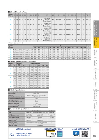
                 QExternal Dimensions Table
                 Cylinder   A AB AC B BA C CA D DA G  H  P1    JB    K    KB   M   MB N   P   PA  PB R
                 I.D. (mm)
                                                      Two-Sided: φ6
                   10  58 12 46 42 41 17 16  6  7  18  5  Depth: 3.5  10  M3×0.5  26 M3×0.5 34 15 M5×0.8  20  10 2.5
 14                                                  Through Hole: φ3.5                                    14
                                                      Two-Sided: φ7.5  20 M4×0.7 Depth 5 34 M4×0.7 47 15 M5×0.8  22  11  3
 Air Cylinders / Valves / Regulators /   Shock Absorbers / O-Rings  20  78 20 58 62 61 25 24 10 10 28  8  Through Hole: φ4.5  20 M4×0.7 Depth 5 44 M4×0.7 55 15 M5×0.8  25  12 3.5  Shock Absorbers / O-Rings  Air Cylinders / Valves / Regulators /
                                                       Depth: 7.2
                                                24
                                           8
                   16
                                                   6
                                              7
                       68 15 53 54 53 21 20
                                                     Through Hole: φ4.5
                                                      Two-Sided: φ7.5
                                                       Depth: 7.2
                                                      Two-Sided: φ7.5
                       81 19 62 73 72 30 29 12
                                                               30 M4×0.7 Depth 6 56 M4×0.7 66 15 M5×0.8
                                                                                               27
                                                                                                  12
                                                34 10
                   25
                                              9
                                                                                                     6
                                                       Depth: 7.2
                                                     Through Hole: φ4.5
                                                      Two-Sided: φ9
 Cylinders and   Accessories  * Values in ( ) are for stroke 10  Through Hole: φ5.5  35 M8×1.25 Depth 10 72  M6×1  83 17  G1/8 40(35) 14 10  Accessories  Cylinders and
                   32
                      108 30 78 96 94 40 38 16 13 42 14
                                                       Depth: 13.2
                                L
 P.951           Cylinder   Two-Sided: φ6 Depth: 3.5 Through Hole: φ3.5  10  20  30  40  50  60  70 LB  80  90  100  125  150  175  200  LC  P.951
                 I.D. (mm)
                                            30
                                                30
                                                        40
                                                    35
                   10
                                                                                70
                                                                                            -
                                                            45
                                                                50
                                                                        60
                                                                    55
                                                                            65
                                                                                                -
                                                                                    -
                                                                                        -
                                                                                                    34
 Shock   Absorber  16  Two-Sided: φ8 Depth: 4.5 Through Hole: φ4.5  30  35  40  45  50  55  60  65  70  75  87.5 100 112.5 125  47  Absorber  Shock
                                                    40
                                                                        65
                                                                                   87.5 100 112.5 125
                                                                                75
                                                35
                                                                            70
                      Two-Sided: φ8 Depth: 4.5 Through Hole: φ4.5
                   20
                                                            50
                                            35
                                                        45
                                                                                                    55
                                                                55
                                                                    60
                   25  Two-Sided: φ8 Depth: 4.5 Through Hole: φ4.5  40  40  45  50  55  60  65  70  75  85  92.5 105 117.5 130  66
 P.991                                                                                                    P.991
                   32  Two-Sided: φ9 Depth: 5.5 Through Hole: φ5.5  45  50  55  60  65  70  75  80  85  90  102.5 115 127.5 140  83
 Rod End   Bearings  QCylinder Theoretical Output Force Table  0.5   0.6   0.7                             Bearings  Rod End
                 Cylinder
                          Compression
                                        Air pressure (MPa)
                      Operating
                   I.D.
                           area
                       Type
                           (mm 2 )
                                            0.4
                  (mm)
                                        0.3
                                    0.2
                                0.1
 P.999             10  Push  157.1   15.7   31.4   47.1   62.8   78.5   94.2   110.0                      P.999
                                10.1
                                                         70.4
                                            40.2
                                                     60.3
                       Pull
                                                 50.3
                                        30.2
                                    20.1
                           100.5
 Floating Joint    16  Push  402.1   40.2   80.4  120.6  160.8  201.1  241.3   281.5                       Floating Joint
                                                        211.1
                                    60.3
                           301.6
                                        90.5  120.6  150.8  181.0
                       Pull
                                30.2
                                    94.2  141.4  188.5  235.6  282.7
                                47.1
                           471.2
 P.1004            20  Push  628.3   62.8  125.7  188.5  251.3  314.2  377.0   439.8                      P.1004
                                                        329.9
                       Pull
                      Push  981.7   98.2  196.3  294.5  392.7  490.9  589.0   687.2
                   25
 Silencer             Push  1608.5   160.8  321.7  482.5  643.4  804.2  965.1  1125.9                      Silencer
                                75.6  151.1  226.7  302.2  377.8  453.3
                                                        528.9
                           755.6
                       Pull
                   32
                       Pull  1206.4   120.6  241.3  361.9  482.5  603.2  723.8   844.5
 P.1006          QCylinder Specifications    10~32                                                        P.1006
 Control Valves   and Accessories  Operating Type  Air (filtered through the filter screen of 40 μm)       and Accessories  Control Valves
                      Cylinder I.D. (mm)
                                           Double Acting
                 Fluid Used
                                           0.15~1 (22~145)
                 Operating Pressure Range Mpa(psi)
 P.1007          Guaranteed Pressure Resistance Mpa(psi)  1.5(215)                                        P.1007
                                             -20~70
                 Operating Temperature °C
                 Operating Speed Range mm/s  30~500
 Air Source   Handling  Stroke Tolerance Range  0~100 0  >0~100 0                                          Handling  Air Source
                 Adjustable Stroke (mm)
                                             -5~0
                                            +1.0
                                                 +1.5
                                           Anti-collision pad
                 Cushion Mechanism
 P.1015          QMagnetic Switch Specification  Electronic Sensor  Reed Sensor                           P.1015
                 Item
                 Type               10V~28V DC  NPN 3-Wire Type PNP 3-Wire Type  5V~240V AC/DC
                                    2-Wire Type
                                                            2-Wire Type
                 Voltage
                                                5V~30V DC
 O-Rings         Max. Switching Current  2.5mA~100mA  30/200mA Max.  10W Max.                              O-Rings
                                                             100mA
                                                6W Max.
                                    2.8W Max.
                 Max. Contact Capacity
                 Internal Consumption Current
                                                5mA Max.
                                                              -
                                    3mA Max.
 P.1027          Leakage Current   0.05mA Max.  0.01mA Max.   -                                           P.1027
                 Protection Circuit  Power polarity reverse protection, surge absorption protection  -
                 Operating Temperature          -10°C~70°C
                 Protection Rating             General IP64
                         MISUMI contact                MISUMI WEB “Chat”           Install MISUMI APP
                                                          MISUMI WEB
                  Tel:   038-959200 or 1382
                  Email: cs@misumi.co.th                                                                 962
                                                     110310658709
          1BSU  @&/ JOEC
          1BSU  @&/ JOEC
   962   963   964   965   966   967   968   969   970   971   972