
Page 113 - MISUMI Thailand Economy Series
P. 113
Format Series Price Ratio Shipping Search Drawing Product Material Table Techinfo Others BD M D GM Format Series Price Ratio Shipping Search Drawing Product Material Table Techinfo Others BD M D GM
Pict
Pict
Title
KW
KW
Title
Name
Name
Date
Date
AK AK
M M
1 1
Ball Screws / Lead Screws / Actuators Alteration Ordering Part Number (1Type · 2D) - 3L - 4T - 5Q - 6S - 7E - 8C - 9J - 0B - (MC·MQ…etc.) Lead Screws / Actuators Ball Screws /
Example
MC4
C-MTSRC16
- 400 - T20 - Q12 - S20 - E8
-
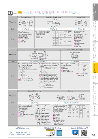
Wrench Flats
Flat Machining
Retaining Ring Groove
m
AE
E
Rolled Ball Screws FW FE FY T S n e E SY SE SW Screws Rolled Ball
Alterations
E
SE(Part E)
FE(Part E)
P.37 Code FE, FW, FY = AE = 0.1mm increments AE(Part E) e tolerance m +0.14 n limit SE, SW, SY=1mm P.37
Machining
Precision Ball Screws FE = Applied on Part E AE13.3 7 8 9 4 5 6 +0.075 0.7 n≥1.2 SE = Applied on Part E Screws Precision Ball
E
increments
0
AE = Applied on Part E
0.5mm increments
Ordering Code
Ordering Code
Ordering Code
0
0.9
FE5-FW10-FY1
SE3-SW10-SY7
AE≤S+T-m-n
0
9.6
E When E<15
EFY≤1.0
P.59 Spec. EFE=0, or FE≥2 10 11.5 -0.09 1.15 n≥1.5 ESE=0, or SE≥2 P.59
12
SW≥E-2
E3≤FW≤20
Support Units for Ball Screw 15 14.3 -0.11 E When 15≤E≤16 for Ball Screw Support Units
14
13.4
0
SW≥E-3
16
15.2
E3≤SY≤20
P.81 Coarse Tapping ME Threaded For Bearing Nut P.81
MC
For bearing nut
M
Motor Brackets Alterations D MC×2 ME×2 E Q BQ Brackets Motor
(MQ×2)
P.91 Code MC = Machining on left end face E Right-hand thread with keyway BQ = Applied on Part Q Q M x pitch P.91
MC(Left End) · ME(Part E)
BQ(Part Q)
Lead Screws ME = Applied on Part E (ME) is applicable to the table BQ20 10 M10×1.0 Lead Screws
M8×1.0
Ordering Code
8
below.
Ordering Code MC8
E
12
ME (Selection range)
M12×1.0
EBQ≤M×3
D·E
MC·ME (Selection range)
9
14
M14×1.0
3
7·8
EBQ≤S, T-Pitch×3
3·4·5
12·13
M17×1.0
17
P.93 5·6 3 3·4 10·11 3·4 EBQ≥Pitch×3 15 M15×1.0 P.93
9·10 3·4·5 14·15 3·4·5·6 X Q = 7·9·16 is not
16
Lead Screw Nuts Spec. XE=3·4 is not applicable X For right-hand thread with applicable Nuts Lead Screw
3·4·5·6·8
11·12
3·4·5·6
13~15 3·4·5·6·8
keyway, E≤8 is not applicable.
16~24 3·4·5·6·8·10
E Keep the wall thickness more
25
3·4·5·6·8·10·12·16
than 1mm. Otherwise you can
P.111 not choose this alternation. P.111
Must be more
than 1mm
Lead Screws Support Units Other alteration Support Units Lead Screws
Tapped hole
P.115 Square Chamfering Keyway b1 P.115
-0.1
-0.3
Q A W 3.2 1.6
Alterations
Stop Plates / Position Indicators S Q C KQ E C KE(J) 3.2 r1 t1 Position Indicators Stop Plates /
P.119 Code ZE(Part E) KQ(Part Q) KE(Part E) P.119
W, A = 1mm increments ZE=E 5~8 W KQ, KE, C = 1mm increments Applicable b1 Keyway Dimension
KQ = Applied on Part Q
ZE = Applied on Part E
Actuators ZE15-W10-A10 11~14 10~14 KE = Applied on Part E diameter Reference Tolerance Reference Tolerance r1 Actuators
shaft
6~10
t1
Ordering Code
8~10
Q·E
Dimension
Dimension
(N9)
Applicable to either Q or E
15~16
1.2
6·7
2
-0.004
Ordering Code
E5≤A≤20
0.08
ES≥A+2 (E/2) √2≤W KQ8-C10 8~10 3 -0.029 1.8 ~0.16
Machining may not be
P.131 Spec. EW is specified by ZE=E possible in some cases, Eb1<C≤60 11·12 4 0 2.5 P.131
0.16
EZE>W due to the relationship ET-C-KQ≥2 13~17 5 -0.030 3 ~0.25
between E and W. ES-C-KE≥2
EKQ(KE)≥2
E Other alterations are
not available to the E When KQ, KE=0,
keyway R will be
same shaft end except eliminated on the
for Coarse Tapping. shaft end side.
MISUMI contact MISUMI WEB “Chat” Install MISUMI APP
MISUMI WEB
Tel: 038-959200 or 1382
Email: cs@misumi.co.th 108
110310581849
1BSU @&/ JOEC
1BSU @&/ JOEC