
Page 149 - MISUMI Thailand Economy Series
P. 149
Format Series Price Ratio Shipping Search Drawing Product Material Table Techinfo Others BD M D GM Format Series Price Ratio Shipping Search Drawing Product Material Table Techinfo Others BD M D GM
KW
Title
KW
Title
Pict
Pict
Date
Name
Name
Date
AK AK
M M
1 1
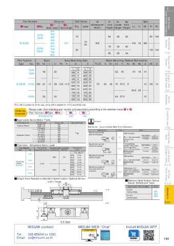
Ball Screws / Lead Screws / Actuators 1Type 2No. Base Length Table Length Dia. Lead Workbench Total Guide Axis L1 t2 Table P1 P2 Lead Screws / Actuators Ball Screws /
Part Number
Ball Screw
Selection
H1
H
W
H2
3L*
4L1
M1
Width
Height Height Height
340
460
1520L
Rolled Ball Screws E-KUA 1510L 400 150 15 10 200 64 28 32 150 12 M6 80 160 Screws Rolled Ball
520
580
20
640
39
79
40
2010L
760
P.37 2020L 700 20 68 28 34 100 150 P.37
820
Precision Ball Screws Part Number W1 H4 Base t1 h1 P3 Base Mounting Hole S P.C.D D Motor Mounting Related Dimensions M2 R Screws Precision Ball
No.
Q
h
Type
N
d
N1
N2
D1
H3
N3
L
S
Q
L
P.59 1510L 49 20 340 6 340 50 62 45 40 15 10 P.59
1520L
Support Units for Ball Screw E-KUA 2010L 195 61 12 29 120 11.5 460 8 460 50 70 50 45 70 57.5 5 12 M5 10 for Ball Screw Support Units
400 8
400 20
520 10
520 20
640 12
640 20
P.81 580 10 580 50 39.5 20 P.81
700 12 700 50
760 20
760 14
Motor Brackets 2020L 55 20 820 14 820 50 64 57.5 12 Brackets Motor
P.91 E*L=340 is suitable for 1510L only, and L=400 is suitable for 1510L and 2010L only. P.91
Please order after selecting part number and parameters according to the selection steps 1 to 4.
Ordering
-
3L
Lead Screws QApplicable Servo Motor Table Output (W) - 340 - 150 Alteration Lead Screws
Part Number (1Type · 2No.) -
4L1
Example
E-KUA1510L
Square Flange
Part Number
Manufacturers
SGM7J-04
400
P.93 Yaskawa Electric SGM7J-02 200 Ball Screw Coupling Side Shaft End Alterations Spec. P.93
HG-MR23
200
Alterations
Code
200
HG-KR23
Lead Screw Nuts Mitsubishi Electric HG-MR43 200 #60 shaft end keyways KC KC Adds keyways. Part Number 3≤KC≤14 Nuts Lead Screw
200
HF-MP23
Machining fixed side
HF-KP23
KC
400
KC = 1mm increments
E-KUA15
HG-KR43
400
Ordering Code
E-KUA20
4≤KC≤19
HF-MP43
400
KC10
HF-KP43
K·S
position of keyways
P.111 QPrecision · Allowable Static Load 400 Vertical *Parallelism Machining fixed side KLC The machining Part Number 4≤K+S≤14 P.111
shaft end keyways
3≤K≤14
can be specified.
E-KUA15
Part Number
Allowable Static Load (kg)
*Positioning
K, S = 1mm increments
Type
Repeatability (mm) Horizontal
(mm)
Lead Screws Support Units 1510L 2897 153 340 Parallelism Machining fixed side K S SC KLC-K5-S2 Part Number 5≤K+S≤19 Support Units Lead Screws
No.
4≤K≤19
Ordering Code
E-KUA20
L
0.06
Adds planes.
SC
shaft end plane
0.07
400
SC = 1mm increments
0.08
460
E-KUA15
5≤SC≤14
1520L
Ordering Code
Screws
P.115 Rolled Ball ±0.05 520 0.09 SC 0.5 SC7 E-KUA20 5≤SC≤19 P.115
0.10
580
E-KUA
2010L 4345 169 640 0.12 Machining a plane at Adds planes at 2 Part Number SWC
fixed side shaft end
0.13
700
Stop Plates / Position Indicators QSingle Axis Actuators Standard Specification Optical Sensor (2 places) SWC 0.5 0.5 SWC SWC = 1mm increments E-KUA15 5≤SWC≤14 Position Indicators Stop Plates /
places (90° position).
760
0.14
2020L
Ordering Code
0.15
820
E-KUA20
5≤SWC≤19
SWC7
Sensor Dimensions Table
P.119 2-φ4.5 Through 28 Q Standard Specification Optical P.119
2.3 20 3.7 Applicable Part Number Code
Actuators 41.5 A E-KUA W1 Actuators
1510L/1520L
W2
E-KUA
W3
10 2010L/2020L
P.131 13.5 A P.131
1
33
2.2
30
A-A View
MISUMI contact MISUMI WEB “Chat” Install MISUMI APP
MISUMI WEB
Tel: 038-959200 or 1382
Email: cs@misumi.co.th 144
110310646379
1BSU @&/ JOEC
1BSU @&/ JOEC