
Page 203 - MISUMI Thailand Economy Series
P. 203
Format Series Price Ratio Shipping Search Drawing Product Material Table Techinfo Others BD M D GM Format Series Price Ratio Shipping Search Drawing Product Material Table Techinfo Others BD M D GM
KW
Title
Pict
KW
Pict
Title
Date
Name
Date
Name
AK AK
M M
1 1
Ball Screws / Lead Screws / Actuators QMaterial / Surface Treatment Carbon Steel Bearing Steel Ball Screw Nut Aluminum Alloy Aluminum Alloy Lead Screws / Actuators Ball Screws /
Components
Linear Guide
Cover
Slide Block
Body
Ball Screw
Material
Aluminum Alloy
SCM415
-
Surface Treatment
Clear Anodized
Clear Anodized
-
-
Clear Anodized
Accessory Name
Rolled Ball Screws QAccessories Motor connection BL / BR / BM Screw End Timing Pulley 10×14(×11) Motor Side (200W) 10×14 Motor Side (400W) Quantity Screws Rolled Ball
Part Number
C-MSX672N-2M(NPN)
Sensor
3
BC
1
Coupling (mm)
Accessories
1
5GT-25 Teeth
Timing Belt
BM
275-5GT-15
P.37 method BL / BR Motor End Timing Pulley 5GT-25 Teeth 1 1 1 P.37
Timing Belt
340-5GT-15
Precision Ball Screws * Panasonic: motor end 11 Screws Precision Ball
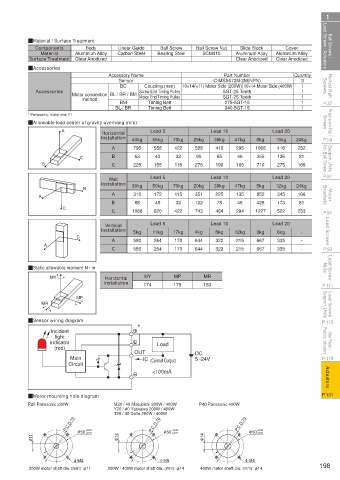
QAllowable load center of gravity overhang (mm)
A
Horizontal
15kg
55kg
6kg
35kg
P.59 Installation 40kg Lead 5 70kg 25kg Lead 10 47kg 1068 Lead 20 24kg P.59
Support Units for Ball Screw B C B 225 155 115 276 190 165 355 136 166 for Ball Screw Support Units
410
295
795
588
422
558
252
416
A
46
81
32
43
95
65
63
275
C
710
P.81 Wall Lead 5 Lead 10 Lead 20 P.81
Installation 30kg 50kg 70kg 20kg 30kg 47kg 5kg 12kg 24kg
B
Motor Brackets A A 310 172 115 351 225 135 852 345 166 Brackets Motor
C B 88 49 32 122 78 46 428 173 81
P.91 C 1066 620 422 743 484 294 1227 522 253 P.91
Lead Screws C Installation 5kg Lead 5 17kg 4kg Lead 10 12kg 3kg Lead 20 - Lead Screws
Vertical
8kg
6kg
11kg
A
322
644
264
215
667
335
170
580
P.93 A C 580 264 170 644 322 215 667 335 - - P.93
Lead Screw Nuts QStatic allowable moment N · m MY MP MR Nuts Lead Screw
Horizontal
P.111 MY Installation 174 175 153 P.111
Lead Screws Support Units MR MP Support Units Lead Screws
P.115 QSensor wiring diagram * P.115
Incident
Stop Plates / Position Indicators indicator Load Position Indicators Stop Plates /
light
(red)
5~24V
P.119 Main OUT IC (Control Output) DC P.119
Circuit
Actuators <100mA Actuators
P.131 QMotor mounting hole diagram P.131
P20 Panasonic 200W M20 / 40 Mitsubishi 200W / 400W P40 Panasonic 400W
Y20 / 40 Yaskawa 200W / 400W
T20 / 40 Delta 200W / 400W
P.C.D.70 P.C.D.70 P.C.D.70
+0.04
+0.04
+0.04
φ 50 +0.01 φ 50 +0.01 φ 50 +0.01
φ 11 φ 14 φ 14
4-M4 4-M5 4-M4
200W motor shaft dia. (mm): φ11 200W / 400W motor shaft dia. (mm): φ14 400W motor shaft dia. (mm): φ14 198
110310668339
1BSU @&/ JOEC
1BSU @&/ JOEC