
Page 231 - MISUMI Thailand Economy Series
P. 231
Format Series Price Ratio Shipping Search Drawing Product Material Table Techinfo Others BD M D GM Format Series Price Ratio Shipping Search Drawing Product Material Table Techinfo Others BD M D GM
Title
KW
Title
Pict
KW
Pict
Name
Name
Date
Date
AK AK
M M
1 1
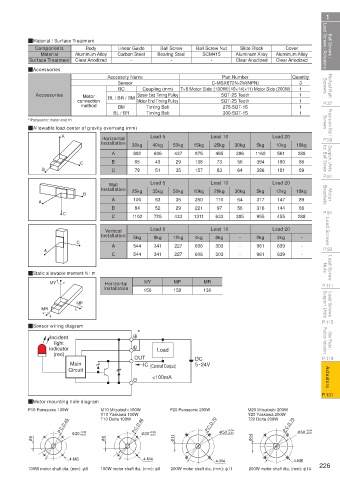
Ball Screws / Lead Screws / Actuators QMaterial / Surface Treatment Carbon Steel Bearing Steel Ball Screw Nut Aluminum Alloy Aluminum Alloy Lead Screws / Actuators Ball Screws /
Slide Block
Components
Ball Screw
Cover
Linear Guide
Body
Aluminum Alloy
Material
SCM415
-
Clear Anodized
Surface Treatment
-
Clear Anodized
-
Clear Anodized
Rolled Ball Screws QAccessories Accessory Name Coupling (mm) 7×8 Motor Side (100W) 10×14(×11) Motor Side (200W) Quantity Screws Rolled Ball
Part Number
Sensor
C-MSX672N-2M(NPN)
3
BC
1
Motor
Motor End Timing Pulley
5GT-25 Teeth
P.37 Accessories connection BL / BR / BM Screw End Timing Pulley 5GT-25 Teeth 1 1 1 1 P.37
method
BM
275-5GT-15
Timing Belt
Precision Ball Screws * Panasonic: motor end 11 Screws Precision Ball
Timing Belt
BL / BR
300-5GT-15
QAllowable load center of gravity overhang (mm)
Horizontal
P.59 A Installation 30kg Lead 5 50kg 15kg Lead 10 30kg 5kg Lead 20 18kg P.59
10kg
25kg
40kg
Support Units for Ball Screw C B 882 606 437 875 485 386 1160 561 288 for Ball Screw Support Units
A
384
180
56
43
29
88
138
65
73
P.81 B C 78 51 35 157 83 64 386 181 89 P.81
Wall Lead 5 Lead 10 Lead 20
Installation
Motor Brackets B A 25kg 35kg 50kg 10kg 20kg 30kg 5kg 12kg 18kg Brackets Motor
250
110
35
63
89
317
100
147
64
A
B 84 52 29 221 97 56 316 144 88
P.91 C C 1102 725 433 1311 633 385 955 455 288 P.91
Lead Screws Installation 5kg Lead 5 12kg 4kg Lead 10 - 2kg Lead 20 - Lead Screws
Vertical
8kg
8kg
3kg
A
P.93 A C C 544 341 227 606 303 - - 961 639 - - P.93
961
227
606
303
544
639
341
Lead Screw Nuts QStatic allowable moment N · m Nuts Lead Screw
MY
MP
Horizontal
P.111 MY Installation 150 150 MR P.111
130
Lead Screws Support Units Mechanical limit of Origin of slide block Effective Stroke 134 Mechanical limit of MR MP Support Units Lead Screws
L
133
slide block
slide block
45±1
P.115 38±1 102 4-M5 Depth 15 φ 10 Pneumatic joint QSensor wiring diagram P.115
Stop Plates / Position Indicators 64 2- φ 5 H7 Depth 12 23 indicator * Position Indicators Stop Plates /
Incident
light
80
Two holes at the same position on the opposite side
50
P.119 7 170 4-M4 Depth 10 92 (red) OUT Load DC P.119
Main IC (Control Output) 5~24V
Actuators 82.5 64 <100mA Actuators
Circuit
50 Effective Stroke + 25 5H7 Depth 7
P.131 102 P.131
85
102 85 1 108 QMotor mounting hole diagram
P10 Panasonic 100W M10 Mitsubishi 100W P20 Panasonic 200W M20 Mitsubishi 200W
φ5 H7 Effective Stroke 7 N-M5 Depth 9 Y10 Yaskawa 100W Y20 Yaskawa 200W
P.C.D.45 P.C.D.46 P.C.D.70 +0.04 P.C.D.70 +0.04
84 M*200 A 83 T10 Delta 100W T20 Delta 200W
+0.01
+0.01
φ 8 φ 30 +0.04 φ 8 φ 30 +0.04 φ 11 φ 50 +0.01 φ 14 φ 50 +0.01
4-M3 4-M4 4-M4 4-M5
100W motor shaft dia. (mm): φ8 100W motor shaft dia. (mm): φ8 200W motor shaft dia. (mm): φ11 200W motor shaft dia. (mm): φ14 226
110310667169
1BSU @&/ JOEC
1BSU @&/ JOEC