
Page 44 - MISUMI Thailand Economy Series
P. 44
Format Series Price Ratio Shipping Search Drawing Product Material Table Techinfo Others BD M D GM Format Series Price Ratio Shipping Search Drawing Product Material Table Techinfo Others BD M D GM
Pict
KW
KW
Title
Title
Pict
Name
Date
Name
Date
AK AK
M M
1 Economy series Alteration Options / Peripheral Products Lead Accuracy Grade Economy series 1
Ball Screws
Ball Screws
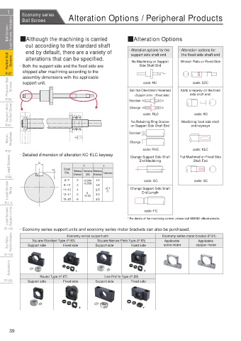
Ball Screws / Lead Screws / Actuators QAlthough the machining is carried QAlteration Options QBall Screw Lead Precision Lead Screws / Actuators Ball Screws /
out according to the standard shaft
Screw Effective Length (lu)
end by default, there are a variety of
error (±ep) and variation (Vu)
Rolled Ball Screws · Both the support side and the fixed side are · Alteration options for the · Alteration options for + Actual Travel Representative Travel Standard Travel Allowable value of representative travel Representative Unit: μm Screws Rolled Ball
support side shaft end
the fixed side shaft end
Nominal Travel
Distance (lo) Line
alterations that can be specified.
Distance (la) Line
Accuracy grade
Screw Effective
No Machining on Support
Wrench Flats on Fixed Side
Length (mm)
C3
C5 (Economy series)
Distance (ls) Line
Distance (lm) Line
Side Shaft End
Representative
Error
Error
P.37 shipped after machining according to the 0’ 0 t More than or Less Travel Distance Variation Travel Distance Variation P.37
assembly dimensions with the applicable
18
23
12
315
8
Precision Ball Screws support unit. Ball Nut Orientation Reversed Adds a keyway on the fixed Travel Distance Error - v 300 315 400 13 10 25 20 Screws Precision Ball
code: NC
code: SZC
500
20
10
27
400
15
12
500
16
23
30
630
(Support side) (Fixed side)
800
630
P.59 Standard side shaft end. 2π v2π 300mm vu ep 1000 1000 18 13 35 25 P.59
40
21
27
800
15
Support Units for Ball Screw Change code: RLC code: KC 1250 1600 29 18 54 35 for Ball Screw Support Units
24
16
1250
30
46
300mm and pitch periodic error (V2π)
P.81 No Retaining Ring Groove Machining fixed side shaft Standard value of variation (V300) relative to displacement Unit: μm P.81
end keyways
on Support Side Shaft End
Accuracy grade C3 C5 (Economy series) C7 (Economy series) C10
Standard
Item
Motor Brackets Change Standard value V300 V2π V300 V2π V300 V300 Brackets Motor
8
6
8
210
18
52
code: RNC
code: KLC
based on ep=2·lu/300·V300.
P.91 · Detailed dimension of alteration KC·KLC keyway Change Support Side Shaft Flat Machined on Fixed Side EC7(Economy series) representative distance error (ep) can be calculated P.91
Lead Screws b t Shaft b t End Machining Shaft End Lead Screws
Dimension
Dimension
(N9)
P.93 6.3 Dia. Reference Tolerance Reference Tolerance code: GC code: SC P.93
6~7
2
-0.004
1.2
Lead Screw Nuts 11~12 3 4 5 -0.03 1.8 +0.1 Change Support Side Shaft Nuts Lead Screw
-0.029
8~10
2.5
0
End Length
0
3.0
13~17
P.111 18~20 6 3.5 Allowable Axial Load Line Diagram Allowable Rotational Speed Line Diagram P.111
Lead Screws Support Units * For details of the machining content, please visit MISUMI official website. 3 2 6 5 4 3 2 10 1.5 5 8 φ32 1.5 3 2 10 2 4 10 1.5 4 8 6 10 8 6 5 4 φ 10 φ 15 Screw shaft O.D. (mm) Support Units Lead Screws
4
code: FC
1.5
φ 20
P.115 · Economy series support units and economy series motor brackets can also be purchased. 1.5 8 4 1.5 3 2 1.5 8 5 6 5 4 φ20 φ25 10 8 6 5 3 8 6 5 4 5 4 3 1.5 3 2 φ 25 φ 32 P.115
10
10
Economy series support unit
Stop Plates / Position Indicators Support side Fixed side Support side Fixed side Economy series motor bracket (P.91) 6 5 4 10 8 6 5 6 5 4 3 1.5 3 2 φ15 4 3 2 1.5 3 2 1.5 2 3 10 8 6 3 Position Indicators Stop Plates /
Applicable
Square-Standard Type (P.83)
Applicable
Square-Narrow Pitch Type (P.85)
stepper motor
servo motor
10
P.119 Allowable Axial Load (N) 1.5 3 2 5 4 3 1.5 2 10000N 10 4 8 6 φ10 Allowable Rotational Speed (min -1 ) 1.5 8 2 10 8 6 5 3 8 6 5 4 3 5 4 3 2 P.119
10
Actuators 10 8 3 1.5 2 4 10 8 6 4 4 3 6 5 4 3 4 3 2 1.5 2 1.5 8 2 Actuators
10
Round Type (P.87) Low Profile Type (P.89) 6 5 10 8 5 4 2 2 1.5 10 2 6 5
P.131 Support side Fixed side Support side Fixed side 4 6 3 1.5 1.5 10 2 8 6 4 P.131
3 5 8 5 3
4 2 10 3 10 6 4
10 2 1.5 2 3 4 5 6 7 8 9 10 3 1.5 2 3 4 5 6 7 8 5 3 2
Fixed - Fixed - Fixed - Supported - 10 2 1.5 2 3 4 5 6 7 8 910 3 1.5 2 3 4 5 6 7
Supported -
Fixed -
Free Fixed Supported Supported Load action point pitch (mm) Fixed - Fixed - Supported Supported Support pitch (mm)
Free
Fixed
Support method Support method
39
1BSU @&/ JOEC
1BSU @&/ JOEC