
Page 139 - MISUMI Thailand Economy Series
P. 139
Format Series Price Ratio Shipping Search Drawing Product Material Table Techinfo Others BD M D GM Format Series Price Ratio Shipping Search Drawing Product Material Table Techinfo Others BD M D GM
Title
KW
Pict
Title
KW
Pict
Name
Date
Name
Date
AK AK
M M
1 1
Ball Screws / Lead Screws / Actuators C-KS40 Lead Block Base Length L2 Motor Bracket Leave Blank Total Maximum Stroke (mm) n Block Qty. Block Qty. Lead Screws / Actuators Ball Screws /
Part Number
Weight (kg)
3
5
6
4
G
Sensors Length L1 Block Qty. Block Qty.
2
1Type
(mm)
Qty.
and Attachments
(mm)
Qty.
1 pcs
2 pcs
1 pcs
2 pcs
-
36
100
(None)
159
2
0.48
-
20
Motor Bracket
W1(1 pcs.)
F0
Rolled Ball Screws (Standard 01 (1 pcs.) 150 Bracket and Attachment W2(2 pcs.) 209 86 34 15 3 0.6 0.67 Screws Rolled Ball
Type)
B1
W3(3 pcs.)
F1
F2
06
B2
Leave Blank
F3
(2 pcs.)
(None)
(Cover Type)
H0
P.37 C-KSC40 200 Without Motor Bracket CW1(1 pcs.) 259 136 84 40 0.72 0.72 P.37
CW2(2 pcs.)
CW3(3 pcs.)
Precision Ball Screws E Double block type is only applicable to base lengths 150 and 200. Screws Precision Ball
E3-sensor type is only applicable to base lengths 150 and 200. (Except for C-KSC4001-B1-100-H0-CW3)
EFor detailed dimensions, please refer to the website.
Part Number (1Type · 2Lead) - 3Block Qty. - 4Base Length - 5Motor Bracket and Attachments - 6Sensor Qty.
Example
P.59 Ordering Please order after selecting part number and parameters according to the selection steps 1 to 6. P.59
-
-
B1
F1
C-KSC4001
-
100
Motor Bracket F0
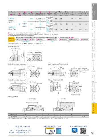
Support Units for Ball Screw Dimensional Drawing of Motor Brackets and Attachments for Ball Screw Support Units
49
Motor Bracket F0
12
25
49
Motor Bracket F0
19
4-M3 Depth 6
P.C.D.29
25
12 19
P.81 12 49 8 φ 20 +0.03 0 0 P.C.D.29 4-M3 Depth 6 P.81
25
19 8 φ 5h75h7 φ 5h7 φ 20 +0.03+0.03 0 20 30 P.C.D.29 4-M3 Depth 6 30°
Motor Brackets 8 φ φ 30 13 13 0.5 0.5 30° 30° 30° Brackets Motor
13 30 0.5 30° 30°
P.91 Motor Bracket and Attachment F1 4-M4 Through Motor Bracket and Attachment F3 P.91
Lead Screws Motor Bracket and Attachment F1 4-M4 Through P.C.D.46 Motor Bracket and Attachment F3 31 4- φ 3.5 Through φ 6 Lead Screws
7.5
49
8.5
49
2.5
3
Motor Bracket and Attachment F1 4-M4 Through
Motor Bracket and Attachment F3
Counterbored Depth 3.5
7.5
49
31
8.5
49
P.C.D.46
4- φ 3.5 Through φ 6
45°
Counterbored Depth 3.5
4- φ 3.5 Through φ 6
2.5
P.93 49 8.5 20 φ 3 3 30 +0.05 0 φ 0 40 40 P.C.D.46 49 7.5 φ 20 2.5 φ 22 +0.05+0.05 22 +0.05 0 0 φ 42 42 31 31 31 4-M3 Through P.93
45° 45°
Counterbored Depth 3.5
4-M3 Through
45°
Lead Screw Nuts φ 20 φ 20 φ 30 +0.05+0.05 φ 0 30 40 45° 45° φ 20 φ 20 φ 022 42 31 4-M3 Through Nuts Lead Screw
P.111 Motor Bracket and Attachment F2 4-M3 Through P.C.D.45 Without Motor Bracket H0 4-M3 Depth 8 P.111
17
14
39.6
Without Motor Bracket H0
Motor Bracket and Attachment F2
8.5
49
12
3.2
Lead Screws Support Units Motor Bracket and Attachment F24-M3 Through P.C.D.45 Without Motor Bracket H0 27 18 4-M3 Depth 8 R2.5 Support Units Lead Screws
178
14
39.6
φ 16
49
8.5
12
3.2
14
17
39.6
45°
4-M3 Through
φ 30 +0.05
8
8.5
49
P.C.D.45
12
3.2 38
4-M3 Depth 8
φ 20
0
R2.5
8
12.5
P.115 φ 20 φ 20 φ 30 +0.05+0.05 φ 0 0 30 38 38 45° 45° 45° 45° 45° φ 5H7 φ 16 φ 16 27 27 18 18 27.6 6 R2.5 P.115
18
12.5 12.5
Stop Plates / Position Indicators Sensor Drawing Standard Type φ 5H75H7 φ Cover Type 27.6 6 6 Position Indicators Stop Plates /
18
18
27.6
P.119 b b e e P.119
a a
Actuators c c f f Actuators
P.131 d d P.131
Dimension a b c d e f
40 Series 42.25 55.3 1.5 11.3 15 12.75
Note: The applicable sensor is L-Shape Photo Microsensors with NPN Type “C-MSX671N-2M”. For detail please refer to P.903.
MISUMI contact MISUMI WEB “Chat” Install MISUMI APP
MISUMI WEB
Tel: 038-959200 or 1382
Email: cs@misumi.co.th 134
110310551789
1BSU @&/ JOEC
1BSU @&/ JOEC