
Page 143 - MISUMI Thailand Economy Series
P. 143
Format Series Price Ratio Shipping Search Drawing Product Material Table Techinfo Others BD M D GM Format Series Price Ratio Shipping Search Drawing Product Material Table Techinfo Others BD M D GM
Pict
Title
Pict
KW
KW
Title
Date
Name
Date
Name
AK AK
M M
1 1
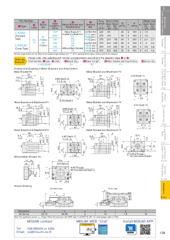
Ball Screws / Lead Screws / Actuators 1Type Lead Block Length L2 Motor Bracket and Sensors Length Block Block (mm) n (mm) m Block Block Lead Screws / Actuators Ball Screws /
Total Maximum Stroke
Part Number
Weight (kg)
4
6
5
3
Base
K
G
2
Qty. Qty.
Qty. Qty.
L1
Qty.
Attachments
Qty.
(mm)
1 pcs 2 pcs
(mm) 1 pcs 2 pcs
Leave Blank (None)
Motor Bracket F0
60
-
-
C-KS60
-
100
200*
50
1.6
-
270
(Standard B1 150* Bracket and Attachment W1(1 pcs.) 220 110 135 25 2 2 3 100 2 2 2 1.5 2.7
F1
W2(2 pcs.)
Rolled Ball Screws C-KSC60 05 (1 pcs.) 400 F3 Leave Blank (None) 470 310 235 50 4 5 100 4 3 3.6 3.3 Screws Rolled Ball
Type)
F2
200
300
2.4
50
210
370
W3(3 pcs.)
10
B2
3
F4
(2 pcs.)
CW1(1 pcs.)
F5
570
50
335
200
500
410
3.9
Without Motor Bracket CW2(2 pcs.)
(Cover Type)
H0
600
510
670
435
CW3(3 pcs.)
P.37 E Only single sliders can be fitted for the guide length marked with "*". EFor detailed dimensions, please refer to the website. 50 6 100 6 4.2 4.6 P.37
Precision Ball Screws Ordering Please order after selecting part number and parameters according to the selection steps 1 to 6. Screws Precision Ball
Part Number (1Type · 2Lead) - 3Block Qty. - 4Base Length - 5Motor Bracket and Attachments - 6Sensor Qty.
Example
C-KSC6005
-
B1
150
F1
-
-
P.59 Dimensional Drawing of Motor Brackets and Attachments Motor Bracket and Attachment F3 P.59
Motor Bracket F0
Support Units for Ball Screw 15.5 30.5 φ 28 +0.03 0 4-M4 Depth 10 18.5 59 10 φ 36 +0.05 0 4-M5 Depth 10 for Ball Screw Support Units
59
18.5
30.5
3
15.5
P.C.D. 40
9
P.81 φ 8h7 30° 45° 9 φ 8h7 φ 26.5 50 P.81
44.5 23 30°
Motor Brackets 0.5 4-M3 Depth 8 45° #60 Brackets Motor
50
59
10
10
59
P.91 Motor Bracket and Attachment F1 0 4-M4 Depth 10 Motor Bracket and Attachment F4 4-M4 Depth 10 P.91
+0.03
φ 38.1 +0.08
18.5
3.5
30.5
18.5
3
30.5
Lead Screws 9 φ 8h7 φ 26.5 φ 30 +0.05 P.C.D. 46 45° 9 φ 8h7 φ 26.5 47.14 Lead Screws
15.5
15.5
P.93 44.5 23 0.5 #42 45° #57.7 P.93
47.14
Lead Screw Nuts Motor Bracket and Attachment F2 0 4-M3 Depth 10 Motor Bracket and Attachment F5 59.6 Nuts Lead Screw
10
59
8
59
18.5
3.5
30.5
30.5
18.5
P.111 15.5 9 φ 8h7 φ 26.5 φ 30 +0.05 P.C.D. 45 45° 15.5 9 φ 8h7 φ 22 +0.05 0 44.5 31 15.5 31 43 P.111
Lead Screws Support Units 44.5 23 0.5 #42 45° 23 0.5 φ 6 Counterbored Depth 4 Support Units Lead Screws
4- φ 3.4 Through
16
18
59.6
P.115 Without Motor Bracket H0 4-M4 Depth 10 P.115
9
15
Stop Plates / Position Indicators φ 30 44 33 φ 6 Counterbored Depth 6 Position Indicators Stop Plates /
4- φ 4 Through
P.119 φ 8 22.5 P.119
33 13.3
Actuators Sensor Drawing Standard Type e e Cover Type Actuators
b
a b a
P.131 P.131
d d f f
c c
Dimension a b c d e f
60 Series 50.75 64.85 3 13 7.8 13
Note: The applicable sensor is L-Shape Photo Microsensors with NPN Type “C-MSX671N-2M”. For detail please refer to P.903.
MISUMI contact MISUMI WEB “Chat” Install MISUMI APP
MISUMI WEB
Tel: 038-959200 or 1382
Email: cs@misumi.co.th 138
110310551609
1BSU @&/ JOEC
1BSU @&/ JOEC