
Page 141 - MISUMI Thailand Economy Series
P. 141
Format Series Price Ratio Shipping Search Drawing Product Material Table Techinfo Others BD M D GM Format Series Price Ratio Shipping Search Drawing Product Material Table Techinfo Others BD M D GM
KW
Title
Pict
Pict
Title
KW
Name
Date
Name
Date
AK AK
M M
1 1
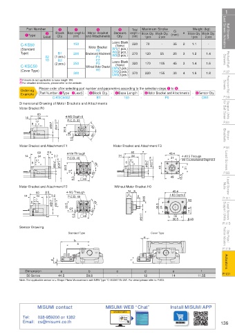
Ball Screws / Lead Screws / Actuators C-KS50 Lead Block Base Length L2 Motor Bracket Leave Blank Total Maximum Stroke (mm) n Block Qty. Block Qty. Lead Screws / Actuators Ball Screws /
Weight (kg)
Part Number
3
5
6
4
G
Sensors Length L1 Block Qty. Block Qty.
2
1Type
(mm)
Qty.
(mm)
and Attachments
Qty.
2 pcs
1 pcs
2 pcs
1 pcs
70
-
2
1.1
-
35
220
150
(None)
Motor Bracket
F0
W2(2 pcs.)
Rolled Ball Screws (Standard 02 (1 pcs.) 200 Bracket and Attachment W1(1 pcs.) 270 120 105 20 3 3 1.2 1.4 Screws Rolled Ball
B1
Type)
55
W3(3 pcs.)
F1
F2
10
B2
Leave Blank
250
F3
45
1.6
320
170
1.4
(2 pcs.)
(None)
H0
(Cover Type)
CW2(2 pcs.)
P.37 C-KSC50 300 Without Motor Bracket CW1(1 pcs.) 370 220 155 30 4 1.6 1.8 P.37
CW3(3 pcs.)
Precision Ball Screws E 2 blocks is not applicable to base length 150. Screws Precision Ball
EFor detailed dimensions, please refer to the website.
Please order after selecting part number and parameters according to the selection steps 1 to 6.
Ordering
Part Number (1Type · 2Lead) - 3Block Qty. - 4Base Length - 5Motor Bracket and Attachments - 6Sensor Qty.
Example
P.59 Dimensional Drawing of Motor Brackets and Attachments - 150 - F0 - CW1 P.59
C-KSC5002
-
B1
Support Units for Ball Screw Motor Bracket F0 4-M3 Depth 6 for Ball Screw Support Units
Motor Bracket F0
Motor Bracket F0
60
60
34
14
60
4-M3 Depth 6
P.C.D. 33
14
34
P.C.D. 33
17
P.C.D. 33
17
P.81 14 8 8 8 17 34 φ 5h75h7 φ 5h7 φ φ 24 +0.03+0.03 φ 24 +0.03 φ 24 0.03.03 0 0.03 4-M3 Depth 6 45° 45° 45° P.81
38.5 38.5
38.5
Motor Brackets 1616 16 0.5 0.5 0.5 45° 45° 45° Brackets Motor
Motor Bracket and Attachment F1 Motor Bracket and Attachment F3
P.91 Motor Bracket and Attachment F1 4-M4 Through Motor Bracket and Attachment F3 49.4 4- φ 3.5 Through P.91
Motor Bracket and Attachment F1
Motor Bracket and Attachment F3
7
8.5
60
60
7
60
8.5
Lead Screws 14 8 8 8 17 60 8.5 3.2 +0.05 0.05 +0.05 +0.05 φ 3030 0.05 0.05 P.C.D. 46 45° 14 8 8 8 17 60 7 φ 5h75h7 φ 5h7 φ φ 22 +0.05+0.05 φ 22 +0.05 φ 22 +0.05+0.05 +0.05 4040 49.4 φ 6 Counterbored Depth3.5 Lead Screws
14
60
34
3.2
14
49.4
34
4-M4 Through
31
4-M4 Through
34
34
4- φ 3.5 Through
31
14
14
3.2
34
P.C.D. 46
4- φ 3.5 Through
34
φ 6 Counterbored Depth3.5
31
17
φ 5h75h7
17
P.C.D. 46
φ 6 Counterbored Depth3.5
17
17
φ 5h7
φ
45°
P.93 φ 30 φ 38.5 38.5 38.5 1616 16 0.5 0.5 #40 45° 45° 45° 45° 40 49 15.5 15.5 15.5 3131 31 P.93
49
Lead Screw Nuts Motor Bracket and Attachment F2 0.5 #40 Without Motor Bracket H0 49.4 Nuts Lead Screw
#40
49
Without Motor Bracket H0
Motor Bracket and Attachment F2
14 9
Without Motor Bracket H0
Motor Bracket and Attachment F2 4-M3 Through
49.4
14 9
60
8.5 3.2
34
14 9 8
49.4
P.C.D. 45
4-M3 Through
11
8.5
P.111 14 8 17 60 8.5 3.2 0.05.05 0.05 0 4-M3 Through 45° 11 8 8 φ 25 φ 25 φ 25 4-M3 Depth 8 R3 P.111
60
4-M3 Depth 8
34
14
11
P.C.D. 45
3.2 +0.05
4-M3 Depth 8 R3
14
34
P.C.D. 45
17
Lead Screws Support Units 8 8 17 φ 5h75h7 φ 5h7 φ φ 30 +0.05 φ 30 φ 30 +0.05 38.5 38.5 38.5 1616 16 0.5 #40 45° 45° 45° 45° 35.5 35.5 35.5 2424 24 32 R3 17.5 17.5 17.5 Support Units Lead Screws
45°
32
32
#40
6.45
36.5
P.115 0.5 0.5 #40 φ 5H75H7 φ 5H7 φ 36.5 6.45 P.115
36.5
6.45
Sensor Drawing
Stop Plates / Position Indicators Standard Type b e e Cover Type Position Indicators Stop Plates /
b
P.119 a a P.119
Actuators d c d c f f Actuators
Dimension a b c d e f
P.131 P.131
50 Series 44.5 59.8 - 12 14 11.55
Note: The applicable sensor is L-Shape Photo Microsensors with NPN Type “C-MSX671N-2M”. For detail please refer to P.903.
MISUMI contact MISUMI WEB “Chat” Install MISUMI APP
MISUMI WEB
Tel: 038-959200 or 1382
Email: cs@misumi.co.th 136
110310551699
+ JOEE
+ JOEE