
Page 167 - MISUMI Thailand Economy Series
P. 167
Format Series Price Ratio Shipping Search Drawing Product Material Table Techinfo Others BD M D GM Format Series Price Ratio Shipping Search Drawing Product Material Table Techinfo Others BD M D GM
Pict
Title
KW
Pict
Title
KW
Date
Date
Name
Name
AK AK
M M
1 1
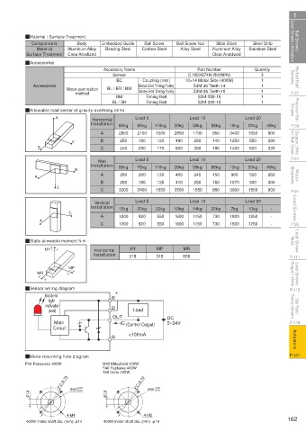
Ball Screws / Lead Screws / Actuators QMaterial / Surface Treatment Embedded Guide Carbon Steel Ball Screw Nut Aluminum Alloy Stainless Steel Lead Screws / Actuators Ball Screws /
Slide Block
Components
Steel Strip
Body
Ball Screw
Bearing Steel
Aluminum Alloy
Alloy Steel
Material
Surface Treatment
-
Clear Anodized
-
-
-
Clear Anodized
Rolled Ball Screws QAccessories Accessory Name Coupling (mm) 10×14 Motor Side (400W) Quantity Screws Rolled Ball
Part Number
Sensor
C-MSX674N-2M(NPN)
3
BC
1
Screw End Timing Pulley
S3M-36 Teeth-10
P.37 Accessories Motor connection BL / BR / BM Motor End Timing Pulley S3M-36 Teeth-14 1 1 1 P.37
method
S3M-258-15
BM
Timing Belt
Precision Ball Screws QAllowable load center of gravity overhang (mm) Timing Belt S3M-300-15 1 Screws Precision Ball
BL / BR
A
Horizontal
22kg
50kg
80kg
P.59 Installation 60kg Lead 5 110kg 30kg Lead 10 88kg 10kg Lead 20 40kg P.59
Support Units for Ball Screw B C B 250 180 120 490 280 140 1250 550 290 for Ball Screw Support Units
2850
2100
1650
3400
2850
1500
A
950
900
1700
330
340
1400
250
170
350
C
620
600
190
P.81 Wall Lead 5 Lead 10 Lead 20 P.81
Installation 55kg 75kg 110kg 35kg 55kg 88kg 12kg 20kg 40kg
B
Motor Brackets A A 280 200 130 400 245 150 900 550 260 Brackets Motor
C B 280 195 125 410 250 150 1070 630 300
P.91 C 3300 2400 1550 2500 1550 950 3000 1800 900 P.91
Lead Screws C Installation 15kg Lead 5 33kg 10kg Lead 10 22kg 1800 Lead 20 - - Lead Screws
Vertical
14kg
7kg
10kg
22kg
730
1150
A
550
1250
1200
1600
820
P.93 A C 1200 820 550 1600 1150 730 1800 1250 - P.93
Lead Screw Nuts QStatic allowable moment N·m MY MP MR Nuts Lead Screw
Horizontal
P.111 MY Installation 318 318 626 P.111
Lead Screws Support Units MR MP Support Units Lead Screws
P.115 QSensor wiring diagram * P.115
Incident
Stop Plates / Position Indicators indicator Load Position Indicators Stop Plates /
light
(red)
5~24V
P.119 Main OUT IC (Control Output) DC P.119
Circuit
Actuators <100mA Actuators
P.131 QMotor mounting hole diagram P.131
P40 Panasonic 400W M40 Mitsubishi 400W
Y40 Yaskawa 400W
T40 Delta 400W
P.C.D.70 +0.04 P.C.D.70 +0.04
φ 14 φ 50+0.01 φ 14 φ 50 +0.01
4-M4 4-M5
400W motor shaft dia. (mm): φ14 400W motor shaft dia. (mm): φ14 162
110310668789
1BSU @&/ JOEC
1BSU @&/ JOEC