
Page 171 - MISUMI Thailand Economy Series
P. 171
Format Series Price Ratio Shipping Search Drawing Product Material Table Techinfo Others BD M D GM Format Series Price Ratio Shipping Search Drawing Product Material Table Techinfo Others BD M D GM
Pict
KW
Title
Pict
Title
KW
Name
Date
Date
Name
AK AK
M M
1 1
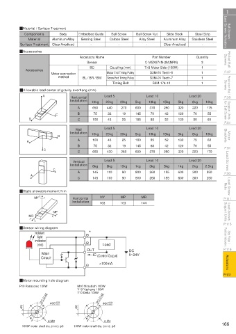
Ball Screws / Lead Screws / Actuators QMaterial / Surface Treatment Embedded Guide Carbon Steel Ball Screw Nut Aluminum Alloy Stainless Steel Lead Screws / Actuators Ball Screws /
Components
Ball Screw
Slide Block
Steel Strip
Body
Alloy Steel
Bearing Steel
Aluminum Alloy
Material
Clear Anodized
-
Surface Treatment
Clear Anodized
-
-
-
Rolled Ball Screws QAccessories Accessory Name C-MSX674N-2M(NPN) Quantity Screws Rolled Ball
Part Number
3
Sensor
BC
Coupling (mm)
P.37 Accessories Motor connection BL / BR / BM Motor End Timing Pulley 7×8 Motor Side (100W) 1 1 1 P.37
S3M-24 Teeth-8
method
Precision Ball Screws QAllowable load center of gravity overhang (mm) Timing Belt S3M-174-10 1 Screws Precision Ball
Screw End Timing Pulley
S3M-24 Teeth-7
P.59 A Installation 10kg Lead 5 30kg 5kg Lead 10 15kg 5kg Lead 20 10kg P.59
Horizontal
10kg
20kg
Support Units for Ball Screw C B 650 440 270 600 370 250 320 220 175 for Ball Screw Support Units
8kg
A
19
42
32
75
120
55
145
70
70
45
85
80
P.81 B C 100 Lead 5 25 185 Lead 10 52 130 Lead 20 60 P.81
Wall
Motor Brackets B Installation 10kg 20kg 30kg 5kg 10kg 15kg 5kg 8kg 10kg Brackets Motor
45
25
180
130
52
85
75
100
A
60
A
B 75 32 19 145 68 42 120 70 55
P.91 C C 650 420 260 600 370 250 320 220 170 P.91
Lead Screws Installation 6kg Lead 5 10kg 1kg Lead 10 5kg 1kg Lead 20 2.5kg Lead Screws
Vertical
8kg
2kg
3kg
A
P.93 A C C 145 110 90 800 260 155 600 300 250 P.93
600
800
260
300
155
250
90
145
110
Lead Screw Nuts QStatic allowable moment N·m Nuts Lead Screw
MP
MY
Horizontal
P.111 MY Installation 103 103 MR P.111
144
Lead Screws Support Units MR MP Support Units Lead Screws
P.115 P.115
QSensor wiring diagram *
Stop Plates / Position Indicators Incident Position Indicators Stop Plates /
light
indicator
P.119 (red) OUT Load DC P.119
Main IC (Control Output) 5~24V
Actuators <100mA Actuators
Circuit
P.131 P.131
QMotor mounting hole diagram
P10 Panasonic 100W M10 Mitsubishi 100W
Y10 Yaskawa 100W
T10 Delta 100W
P.C.D.45 +0.04 P.C.D.46
+0.01
φ 8 φ 30 +0.01 φ 8 φ 30 +0.04
4-M3 4-M4
100W motor shaft dia. (mm): φ8 100W motor shaft dia. (mm): φ8 166
110310673109
1BSU @&/ JOEC
1BSU @&/ JOEC