Page 187 - MISUMI Thailand Economy Series
P. 187

Format  Series   Price Ratio  Shipping  Search   Drawing  Product   Material  Table   Techinfo Others  BD  M  D  GM  Format  Series   Price Ratio  Shipping  Search   Drawing  Product   Material  Table   Techinfo Others  BD  M  D  GM
                                                   Pict
                                                               Title
 KW
                                      KW
 Title
 Pict
 Date
 Name
                   Name
                                Date
 AK      AK
 M       M
 1                                                                                                         1
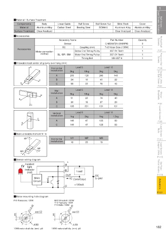
 Ball Screws /    Lead Screws / Actuators  QMaterial / Surface Treatment  Carbon Steel  Bearing Steel   Ball Screw Nut  Aluminum Alloy  Aluminum Alloy  Lead Screws / Actuators  Ball Screws /
                                                                                               Cover
                                            Linear Guide
                   Components
                                  Body
                                                                                 Slide Block
                                                         Ball Screw
                                                                      SCM415
                     Material
                               Aluminum Alloy
                                                            -
                                                                                Clear Anodized
                               Clear Anodized
                 Surface Treatment
                                                -
                                                                        -
                                                                                            Clear Anodized
 Rolled Ball   Screws  QAccessories          Accessory Name               C-MSX672N-2M(NPN)   Quantity     Screws  Rolled Ball
                                                                             Part Number
                                                                                                 3
                                                Sensor
                                                          Coupling (mm)
                                               BC
 P.37              Accessories  Motor connection   BL / BR / BM  Screw End Timing Pulley  7×8 Motor Side (100W)  1 1 1  P.37
                                                                             3GT-24 Teeth
                                  method
 Precision Ball   Screws  QAllowable load center of gravity overhang (mm)  Timing Belt  189-3GT-9  1       Screws  Precision Ball
                                                                             3GT-24 Teeth
                                                       Motor End Timing Pulley
 P.59                      A            Installation  5kg  Lead 5  10kg  3kg  Lead 10  5kg                P.59
                                        Horizontal
 Support Units    for Ball Screw  C        A        280      120      245      140                         for Ball Screw  Support Units
                                           B
                                                             10
                                                                                22
                                                    24
                                                                       40
 P.81                B                     C        55  Lead 5  22     78  Lead 10  43                    P.81
                                          Wall
 Motor   Brackets                 B     Installation  5kg    10kg     3kg      5kg                         Brackets  Motor
                                           A
                                                                       74
                                                                                40
                                                    51
                                                             20
                    A
                                           B        30       15        37       20
 P.91                      C               C        195      231      131      131                        P.91
 Lead Screws                            Installation  1kg  Lead 5  3kg  1kg  Lead 10 1.5kg                 Lead Screws
                                         Vertical
 P.93                 A         C          A        140      47       125       83                        P.93
                                                             47
                                                                                83
                                                                      125
                                                    140
                                           C
 Lead Screw   Nuts  QStatic allowable moment N · m                                                         Nuts  Lead Screw
                                        Horizontal
 P.111                 MY               Installation  MY     MP       MR                                  P.111
                                                    16
                                                             20
                                                                       19
 Lead Screws   Support Units  MR  MP                                                                       Support Units  Lead Screws
 P.115                                                                                                    P.115
                 QSensor wiring diagram           *
 Stop Plates /    Position Indicators  indicator                                                           Position Indicators  Stop Plates /
                        Incident
                         light
 P.119                   (red)                   OUT    Load        DC                                    P.119
                              Main                  IC  (Control Output)  5~24V
 Actuators                   Circuit                   <100mA                                              Actuators
 P.131                                                                                                    P.131
                 QMotor mounting hole diagram
                 P10 Panasonic 100W       M10 Mitsubishi 100W
                                          Y10 Yaskawa 100W
                                          T10 Delta 100W
                           P.C.D.45                P.C.D.46
                                                        +0.01
                                 +0.01
                  φ 8         φ 30 +0.04  φ 8        φ 30 +0.04
                             4-M3                     4-M4
                 100W motor shaft dia. (mm): φ8  100W motor shaft dia. (mm): φ8                          182


                                                     110310668699

          1BSU  @&/ JOEC
          1BSU  @&/ JOEC
   182   183   184   185   186   187   188   189   190   191   192