
Page 191 - MISUMI Thailand Economy Series
P. 191
Format Series Price Ratio Shipping Search Drawing Product Material Table Techinfo Others BD M D GM Format Series Price Ratio Shipping Search Drawing Product Material Table Techinfo Others BD M D GM
Pict
Title
KW
Title
KW
Pict
Name
Date
Date
Name
AK AK
M M
1 1
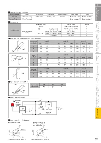
Ball Screws / Lead Screws / Actuators QMaterial / Surface Treatment Carbon Steel Bearing Steel Ball Screw Nut Aluminum Alloy Aluminum Alloy Lead Screws / Actuators Ball Screws /
Slide Block
Components
Body
Linear Guide
Ball Screw
Cover
SCM415
Aluminum Alloy
Material
Clear Anodized
-
Clear Anodized
-
Clear Anodized
-
Surface Treatment
Rolled Ball Screws QAccessories Accessory Name C-MSX672N-2M(NPN) Quantity Screws Rolled Ball
Part Number
3
Sensor
Coupling (mm)
BC
P.37 Accessories Motor connection BL / BR / BM Screw End Timing Pulley 7×8 Motor Side (100W) 1 1 1 P.37
3GT-24 Teeth
method
Precision Ball Screws QAllowable load center of gravity overhang (mm) Timing Belt 189-3GT-9 1 Screws Precision Ball
3GT-24 Teeth
Motor End Timing Pulley
P.59 A Installation 10kg Lead 5 - 3kg Lead 10 15kg 3kg Lead 20 10kg P.59
Horizontal
Support Units for Ball Screw C B 500 125 - - 790 280 135 325 156 87 for Ball Screw Support Units
6kg
30kg
8kg
A
49
145
30
43
10
119
23
55
107
24
93
P.81 B C 107 Lead 5 - 310 Lead 10 50 198 Lead 20 52 P.81
Wall
Motor Brackets B Installation 15kg 30kg - - 3kg 8kg 15kg 3kg 6kg 10kg Brackets Motor
48
104
50
193
91
22
304
63
A
A
B 25 9 - 140 48 22 116 54 30
P.91 C C 304 119 - 776 273 131 321 153 86 P.91
Lead Screws Installation 2kg Lead 5 10kg 1kg Lead 10 5kg 1kg Lead 20 - Lead Screws
Vertical
2kg
2kg
4kg
A
P.93 A C C 250 125 50 446 223 89 353 177 - - P.93
446
223
125
89
177
353
50
250
Lead Screw Nuts QStatic allowable moment N · m Nuts Lead Screw
Horizontal
P.111 MY Installation MY MP MR P.111
70
75
80
Lead Screws Support Units MR MP Support Units Lead Screws
P.115 P.115
QSensor wiring diagram *
Stop Plates / Position Indicators indicator Position Indicators Stop Plates /
Incident
light
P.119 (red) OUT Load DC P.119
Main IC (Control Output) 5~24V
Actuators Circuit <100mA Actuators
P.131 P.131
QMotor mounting hole diagram
P10 Panasonic 100W M10 Mitsubishi 100W
Y10 Yaskawa 100W
T10 Delta 100W
P.C.D.45 P.C.D.46
+0.01
+0.01
φ 8 φ 30 +0.04 φ 8 φ 30 +0.04
4-M3 4-M4
100W motor shaft dia. (mm): φ8 100W motor shaft dia. (mm): φ8 186
110310668609
1BSU @&/ JOEC
1BSU @&/ JOEC