
Page 195 - MISUMI Thailand Economy Series
P. 195
Format Series Price Ratio Shipping Search Drawing Product Material Table Techinfo Others BD M D GM Format Series Price Ratio Shipping Search Drawing Product Material Table Techinfo Others BD M D GM
Pict
KW
Title
Title
KW
Pict
Date
Name
Name
Date
AK AK
M M
1 1
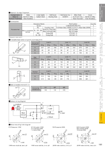
Ball Screws / Lead Screws / Actuators QMaterial / Surface Treatment Carbon Steel Bearing Steel Ball Screw Nut Aluminum Alloy Aluminum Alloy Lead Screws / Actuators Ball Screws /
Cover
Slide Block
Ball Screw
Body
Linear Guide
Components
SCM415
Material
Aluminum Alloy
Clear Anodized
-
Surface Treatment
-
Clear Anodized
Clear Anodized
-
Rolled Ball Screws QAccessories Accessory Name Coupling (mm) 7×8 Motor Side (100W) 10×14(×11) Motor Side (200W) Quantity Screws Rolled Ball
Part Number
C-MSX672N-2M(NPN)
3
Sensor
BC
1
Motor End Timing Pulley
5GT-25 Teeth
method
P.37 Accessories Motor connection BL / BR / BM Screw End Timing Pulley 5GT-25 Teeth 1 1 1 1 P.37
Timing Belt
BM
275-5GT-15
Precision Ball Screws * Panasonic: motor end 11 Screws Precision Ball
340-5GT-15
Timing Belt
BL / BR
QAllowable load center of gravity overhang (mm)
Horizontal
P.59 A Installation 30kg Lead 5 50kg 15kg Lead 10 30kg 5kg Lead 20 18kg P.59
40kg
10kg
25kg
Support Units for Ball Screw C B 547 391 298 521 298 242 675 330 175 for Ball Screw Support Units
A
37
224
29
84
22
42
47
107
55
P.81 B C 42 29 21 80 44 35 193 93 48 P.81
Wall Lead 5 Lead 10 Lead 20
Installation
Motor Brackets B A 25kg 35kg 50kg 10kg 20kg 30kg 6kg 12kg 18kg Brackets Motor
48
58
21
35
76
160
124
35
52
A
B 53 35 22 131 61 37 185 88 55
P.91 C C 670 455 298 770 382 242 562 272 175 P.91
Lead Screws Installation 5kg Lead 5 12kg 4kg Lead 10 - 2kg Lead 20 - Lead Screws
Vertical
8kg
8kg
3kg
A
P.93 A C C 310 192 129 344 172 - - 546 364 - - P.93
172
364
546
344
192
310
129
Lead Screw Nuts QStatic allowable moment N · m Nuts Lead Screw
MY
MP
Horizontal
P.111 MY Installation 110 110 MR P.111
120
Lead Screws Support Units MR MP Support Units Lead Screws
P.115 QSensor wiring diagram P.115
Stop Plates / Position Indicators indicator * Position Indicators Stop Plates /
Incident
light
P.119 (Red) OUT Load DC P.119
Main IC (Control Output) 5~24V
Actuators <100mA Actuators
Circuit
P.131 P.131
QMotor mounting hole diagram
P10 Panasonic 100W M10 Mitsubishi 100W P20 Panasonic 200W M20 Mitsubishi 200W
Y10 Yaskawa 100W Y20 Yaskawa 200W
T10 Delta 100W
T20 Delta 200W
P.C.D.45 P.C.D.46 P.C.D.70 +0.04 P.C.D.70 +0.04
+0.01
+0.01
φ 8 φ 30 +0.04 φ 8 φ 30 +0.04 φ 11 φ 50 +0.01 φ 14 φ 50 +0.01
4-M3 4-M4 4-M4 4-M5
100W motor shaft dia. (mm): φ8 100W motor shaft dia. (mm): φ8 200W motor shaft dia. (mm): φ11 200W motor shaft dia. (mm): φ14 190
110310668519
1BSU @&/ JOEC
1BSU @&/ JOEC