
Page 299 - MISUMI Thailand Economy Series
P. 299
Format Series Price Ratio Shipping Search Drawing Product Material Table Techinfo Others BD M D GM Format Series Price Ratio Shipping Search Drawing Product Material Table Techinfo Others BD M D GM
KW
Title
KW
Pict
Title
Pict
Name
Name
Date
Date
AK AK
M M
1 1
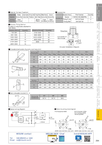
Ball Screws / Lead Screws / Actuators QMaterial / Surface Treatment Cover QAccessories Sensor C-MSX672N-2M(NPN) Quantity Lead Screws / Actuators Ball Screws /
Part Number
Linear Guide Timing Belt Timing Pulley Slide Block
Body
Accessory Name
Components
3
Material Aluminum Alloy Carbon Steel Rubber 45C Steel Aluminum Alloy Aluminum Alloy
Surface
Nickel
Clear
Clear
Clear
Treatment Anodized - - Plated Anodized Anodized Accessories Timing Pulley 5GT-25 Teeth 2 1
Timing Belt
340-5GT-25
Rolled Ball Screws QActuator Fixing Method Screws Rolled Ball
Number of fixing blocks attached for
each stroke
P.37 Effective Stroke Quantity Effective Stroke Quantity Fixing Block P.37
3100~3500
100~500
4
16
Precision Ball Screws 1100~1500 10 4100~4V500 18 φ 5.5 Through 105 Screws Precision Ball
600~1000
6
3600~4000
88
2- φ 10 Depth 5.5
8
20
22
1600~2000
4600~5000
25
P.59 2100~2500 12 5500 24 8.5 30 19 15.5 P.59
14
2600~3000
Support Units for Ball Screw QAllowable load center of gravity overhang (mm) Actuator Installation Diagram for Ball Screw Support Units
50
7:1
3:1
10:1
5:1
Horizontal
P.81 A Installation 10kg 20kg 30kg 25kg 35kg 45kg 28kg 40kg 55kg 30kg 45kg 60kg P.81
A
Motor Brackets C B 950 420 250 950 625 450 1300 850 550 1850 1250 800 Brackets Motor
50
145
105
90
50
90
55
140
145
55
90
250
15
15
18
C
15
P.91 B Wall 42 3:1 10 24 5:1 10 25 7:1 10 25 10:1 10 P.91
Lead Screws A B Installation 10kg 20kg 30kg 25kg 35kg 45kg 28kg 40kg 55kg 30kg 45kg 60kg Lead Screws
10
25
15
15
25
10
10
15
25
42
10
19
A
90
60
60
90
90
140
60
145
60
P.93 C B 250 110 260 140 600 450 1300 850 550 1950 1150 800 P.93
C
450
950
950
Lead Screw Nuts Installation 3kg 6kg 9kg 5kg 10kg 15kg 6kg 12kg 16kg 6kg 13kg 17kg Nuts Lead Screw
10:1
7:1
3:1
5:1
Vertical
A
P.111 A C C 900 450 300 900 450 300 900 450 300 900 450 300 P.111
300
300
300
900
900
450
450
450
900
900
300
450
Lead Screws Support Units QStatic allowable moment N · m Support Units Lead Screws
MP
MR
MY
Horizontal
P.115 MY Installation 337.9 337.9 58.6 P.115
Stop Plates / Position Indicators MR MP Position Indicators Stop Plates /
P.119 P.119
QSensor wiring diagram * QMotor mounting hole diagram
Actuators indicator Load P40 Panasonic 400W M40 Mitsubishi 400W Actuators
Incident
Y40 Yaskawa 400W
light
T40 Delta 400W
(red)
5~24V
P.131 Main OUT IC (Control Output) DC P.C.D.70 +0.04 P.C.D.70 +0.04 P.131
Circuit φ 50+0.01 φ 50+0.01
<100mA φ 14 φ 14
4-M4 4-M5
400W motor shaft dia. (mm): φ14 400W motor shaft dia. (mm): φ14
MISUMI contact MISUMI WEB “Chat” Install MISUMI APP
MISUMI WEB
Tel: 038-959200 or 1382
Email: cs@misumi.co.th 294
110310673469
1BSU @&/ JOEC
1BSU @&/ JOEC