
Page 799 - MISUMI Thailand Economy Series
P. 799
Format Series Price Ratio Shipping Search Drawing Product Material Table Techinfo Others BD M D GM Format Series Price Ratio Shipping Search Drawing Product Material Table Techinfo Others BD M D GM
Title
Pict
Title
KW
Pict
KW
Name
Name
Date
Date
AK AK
M M
Economy series Product Overview Product Overview Economy series
Motorized Positioning Stages Motorized Positioning Stages
QConnector Pin Configuration QConnecting Diagram
vs Standard Type Sensor Substrate
Saving
Economy series up to Foot Position Power Supply 24V GND Vout CW
Signal Definition
Vin
1
Motorized Positioning 51 % 2 3 CW Reverse (Rear) Limit ORG
CCW Positive (Front) Limit
Stages 4 5 6 Power Supply 0V Black CCW
Origin
A+
7 A- Green
Linear Ball Guide Type 8 B+ Red MOTOR
9 B- Blue 9
Long Stroke Quick Positioning 10 Spare
11 Spare
Diverse Combinations 12 Spare Screws / Positioning Stages Locating Pins / Bushings / Clamping
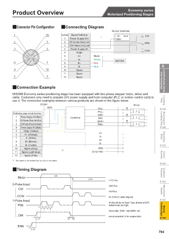
QConnection Example
QFeature MISUMI Economy series positioning stage has been equipped with two-phase stepper motor, driver and
cable. Customers only need to prepare 24V power supply and host computer (PLC or motion control card) to
use it. The connection examples between various products are shown in the figure below. Pins Locating
Added positioning holes on the
Shorten ball spacing upper and lower tables for quick DC24V Driver
for long stroke positioning GND PUL+ R
Low Price achieved PUL- P.745
by standardizing the Positioning stage end pin function
1 Low price is achieved by simplifying the structure assembly circuit 1 Power Supply 24V (Red) DIR+ R
and sharing the parts. board and motor. 2 CW Reverse (Rear) Limit (Blue) Controller DIR- Locating Pins Bushings for
2 Quick positioning is achieved by adding 3 CCW Positive (Front) Limit (Green) ENA+ R
positioning holes to the upper and lower seats of 4 Power Supply 0V (Black) ENA- P.749
the stage. 5 Origin (Yellow)
3 Long stroke is achieved by rearranging the balls 6 A+ (Orange) A+
and extending the lower seat, etc. Cross 7 A- (White) A- Bolts Adjusting
4 The aperture and position of the whole series of orthogonal and 8 B+ (Brown) B+
positioning holes are common to achieve mutual equally spaced 9 B- (Purple) B- P.753
positioning holes are
grouping and diversity of combinations. added to the upper/lower table 10 Spare (Grey) GND
for diverse combinations *1
11 Spare (Light Blue) DC12~50V
12 Spare (Pink) Screws Clamp
QUniversal Specifications *1. The cable in the dotted box is a 2m or 4m cable.
P.760
Feed Screw Ball Screw φ6, Lead 1mm
QTiming Diagram
Guide Linear Ball Guide Type Pushers Urethane
Motor CW
Type 2-Phase Stepper Motor 1.3A / Phase CCW t1<0.1us
Motor P.763
Step Angle 1.8° 2-Pulse Input t2≥0.9us
CW
Part Number HR10A-10J-12P (HIROSE) t3≥10us Heads Micrometer
Connector
Receiving Side Part Number HR10A-10P-12S (HIROSE) CCW t4: ENA (Enable Signal)
1-Pulse Input P.767
Power Voltage DC24V±10% t4 should be at least 10μs ahead of DIR,
PUL determined as high.
Sensor Type Photomicro Sensor EE-SX4320 (OMRON) t1 t2 t1 t2
Sensor Substrate Generally, ENA+ and ENA- are Positioning Stages Motorized
Control Output NPN Open Collector Output
DIR recommended to be suspended.
Output Logic When detecting (shading): output transistor OFF (non-conductive) t1 t3 t1 t3 P.769
ENA
t1 t4
794
1BSU @&/ JOEC
1BSU @&/ JOEC