Page 801 - MISUMI Thailand Economy Series
P. 801

Format  Series   Price Ratio  Shipping  Search   Drawing  Product   Material  Table   Techinfo Others  BD  M  D  GM  Format  Series   Price Ratio  Shipping  Search   Drawing  Product   Material  Table   Techinfo Others  BD  M  D  GM
 KW
                                      KW
 Pict
 Title
                                                               Title
                                                   Pict
 Date
                   Name
                                Date
 Name
 AK      AK
 M       M
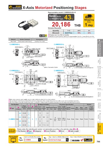
 Economy series  Product Overview Motorized Positioning Stages   X-Axis Motorized Positioning Stages
 Motorized Positioning Stages
                                                         Representative model: C-XMBS630-R-A-2
 QDriver                                                  Save Up to
                                                          vs Standard Type  43%              Shipping
 Two-Phase   Pulse Signal Voltage (V)  Power Voltage (V)  Output Current (A)  Subdivision  Pulse Input Mode  from
 Stepper motor                                              20,186
 Driver  5~24  DC12~50  0.1~2.2  200~51200  2-Pulse (CW/CCW) /                     THB 1 day
 1-Pulse(Step/Dir)
                                                         Volume Discount
 QCurrent Setting  QSubdivision Setting  QPulse Input Mode   Quantity       1~3       4~5        6~
                                                             Discount     Unit Price  15%       30%
                                                         E  Shipping days may differ by Quantity.
 Constant Value  SW1  SW2  SW3  SW4  Steps / Revolution  SW5  SW6  SW7  SW8  Mode  SW11  SW12  E Quantity of volume discount above is for representative Part No. It may differ by the Part.
 Default[0.1A]  on  on  on  on  Default[200]  on  on  on  on  2-Pulse   off  on
                                             Accessories
                            Surface Treatment
                    Material
 0.2A  off  on  on  on  400  off  on  on  on  (CW/CCW)  Alloy Steel  Electroless Nickel Plating  Locating Pins: 4 pcs  9
 0.3A  on  off  on  on  800  on  off  on  on  1-Pulse  off  off
 0.5A  off  off  on  on  1600  off  off  on  on  (Step/Dir)  C-XMBS420-L  C-XMBS630-L  #60
                                                                             #60
                                  #40
 0.6A  on  on  off  on  3200  on  on  off  on  φ 4H7 Depth 4  4  #40  8-M4 Depth 6  50
                                                                             50
                       φ 4H7 Depth
                                                                 8-M4 Depth 6
                                   32
                                   32
                                                                             32
                                                       φ 4H7 Depth 4  4
 0.7A  off  on  off  on  3600  off  on  off  on  2-  φ 3H7 Through  φ 4H7 Depth  32                        Screws / Positioning Stages  Locating Pins / Bushings / Clamping
                                       2-  φ 3H7 Through
 0.8A  on  off  off  on  6400  on  off  off  on  32  32  32  32
 1.0A  off  off  off  on  12800  off  off  off  on  1  1      50  50   50  50  32  32
 1.2A  on  on  on  off  1000  on  on  on  off  4-M3 Depth 6                  1  1
                                     +0.02 Depth 4
                                     +0.02
                                                                                   2-  φ 3H7 Through
                                                                                   2-  φ 3H7 Through
 1.3A  off  on  on  off  2000  off  on  on  off  11.5  11.5  4 0 Depth 4  4-M3 Depth 6  4-M3 Through  +0.02 Depth 4
                                                                   4-M3 Through
                                    4 0
 1.5A  on  off  on  off  4000  on  off  on  off  106.5                   11.5  11.5  4 4 0 0 +0.02  Depth 4
                                       106.5
                                 4- φ3.4 Counterbored Hole φ6 Depth 3.4
 1.6A  off  off  on  off  5000  off  off  on  off  4- φ3.4 Counterbored Hole φ6 Depth 3.4  126.5           Pins  Locating
                                                                                 126.5
 1.7A  on  on  off  off  7200  on  on  off  off  24  24  20  20
 1.8A  off  on  off  off  8000  off  on  off  off  4  4  32             24  24  20  20                    P.745
                                   32
                                                     Motor Connector Cable
                                                                             50
                                                                                   4-  φ 4.5 Counterbored Hole  φ 8 Depth 4.6
 2.0A  on  off  off  off  10000  on  off  off  off   Motor Connector Cable  4  4  50  4-  φ 4.5 Counterbored Hole  φ 8 Depth 4.6
                                      100
                                      100
 2.2A  off  off  off  off  51200  off  off  off  off  C-XMBS650-L  #60  20  C-XMBS820-L  #80
                                            20
                                      #60
                                                                                #80
                       8-M4 Depth 6
                       8-M4 Depth 6   50                          8-M4 Depth 6   70                        Locating Pins  Bushings for
                                                                                 70
                                      50
                                                                  8-M4 Depth 6
                                      32
                                                                                 32
                  φ4H7 Depth
                  φ4H7 Depth 4  4     32                                         32
 QExample of Use                                                                       φ 4H7 Depth
                                                                                       φ 4H7 Depth 4  4
                                                                                                          P.749
 Application Name: Motor Installation Error Simulation Testing Machine  50  50  50  50  32  32
                                      1  1                      70  70   70  70  32  32
 Application: A magnet is fixed at the front end of the motor output shaft and the PCB inspection substrate is
                                             2-  φ 3H7 Through
                                             2-  φ 3H7 Through
                           4-M3 Through
 fixed on the positioning stage to make the magnet close to the PCB inspection center.  4-M3 Through  4 4 0 0  Depth 4  1  1  11.5  11.5  Bolts  Adjusting
                                         +0.02 Depth 4
                                         +0.02
                                                                     2- φ3H7 Through
 The actual installation error of the motor is simulated by the motorized positioning stage position   11.5  11.5  2- φ3H7 Through  4 0 Depth 4
                                                                                   +0.02
                                                                                   +0.02 Depth 4
                                          166.5
 transformation, and the PCB will detect and record the electrical signal when the motor output shaft is in   166.5  4 0  P.753
                                                                            146.5
 different positions.         24  24  20  20                                146.5
                                      50    4-  φ 4.5 Counterbored Hole  φ 8 Depth 4.6  26  26  25  25  2  2
                                      50
                                            4-  φ 4.5 Counterbored Hole  φ 8 Depth 4.6
                                4  4                                                                       Screws  Clamp
                                                                                4-  φ 4.5 Counterbored Hole  φ 8 Depth 4.5
                                                                         70     4-  φ 4.5 Counterbored Hole  φ 8 Depth 4.5
                                                                         70
                 EMotor side connector cable lengths vary by model, which are subject to the actual products.  P.760
                 EThe purchased model already includes the positioning stage body, the corresponding driver and cable, so no need to purchase separately.
                 EThe above figure shows the model when cover L is selected. Please check the detailed dimensions by CAD data when selecting the cover R.
                    Part Number                Mechanical Specification  Accuracy Specification  Sensor
                                            5
                               Stage   3    4    Cable  Travel                                             Pushers  Urethane
                                                                  One-Way   Repetitive
                                                                                                  Origin
                                                   Load
 Economy Series Motorized Positioning Stages   1Type  2   Surface  Cover    Driver Length  Distance   Capacity    Weight   Resolution   Maximum    Positioning  Positioning   Invalid    Parallelism  Motion    Motion    Limit    Sensor
                        Category  (mm)  Position  (m)  (mm)  (N)  (kg)  (Pulse)  Speed  Accuracy Accuracy  Motion  Straightness Parallelism Sensor  (ORG1)
 Z-Axis                                                                                                   P.763
                           420  40×40  L        18     0.4
                                     R
                                     L
                           630  60×60  R        28  98  0.6    10                                          Heads  Micrometer
 Economy Series Motorized Positioning Stages   C-XMBS X-Axis  L  A  2 4  5μm  mm/  Within  Within   10μm 30μm 10μm  20μm Provided Provided
                                                                  20μm ±5.0μm
                           650 60×100           43     0.8     sec
 XY-Axis                             R                                                                    P.767
                           820  80×80  L        20  117.6  0.8
                                     R
                          Please order after selecting part number and parameters according to the selection steps 1 to 5.  Positioning Stages  Motorized
                 Ordering
                  Example  Part Number (1Type · 2Category) - 3Cover Position -  4Driver  -  5Cable Length
                                  C-XMBS630        -      L      -    A   -       2                       P.769
                 How to search   Search on MISUMI official website    Step 1   Search on MISUMI official website  Step 2   Select MISUMI economy series brand
                  on website  By                    By
                           Type  C-XMBS            Keyword  motorized stage
                                                                                                         796
                                                     110310551069

          1BSU  @&/ JOEC
          1BSU  @&/ JOEC
   796   797   798   799   800   801   802   803   804   805   806