
Page 802 - MISUMI Thailand Economy Series
P. 802
Format Series Price Ratio Shipping Search Drawing Product Material Table Techinfo Others BD M D GM Format Series Price Ratio Shipping Search Drawing Product Material Table Techinfo Others BD M D GM
KW
Pict
KW
Title
Title
Pict
Name
Date
Date
Name
AK AK
M M
XY-Axis Motorized Positioning Stages
Representative model: C-XYMBS630-R-A-2
Save Up to
vs Standard Type 46% Shipping
40,339 THB 10 days
from
Volume Discount
Quantity 1~3 4~5 6~
Discount Unit Price 15% 30%
E Shipping days may differ by Quantity.
E Quantity of volume discount above is for representative Part No. It may differ by the Part.
Surface Treatment
Accessories
Material
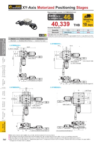
9 Alloy Steel Electroless Nickel Plating Locating Pins: 4 pcs C-XYMBS630-L
Locating Pins / Bushings / Clamping Screws / Positioning Stages 2- φ 3H7 Through 11.5 11.5 40 40 106.5 106.5 11.5 11.5 11.5 60 32 126.5 126.5
C-XYMBS420-L
11.5
60
60
126.5
40
2- φ 3H7 Through
50
50
106.5
32 60
32
32
32
11.5
126.5
50
2- φ 3H7 Through
106.5
11.5
32
50
40
2- φ 3H7 Through
32
40
32
40
32
32
Locating Pins 106.5 106.5 40 106.5 32 106.540 32 4-M3 Depth 64-M3 Depth 6 126.5 60 60 126.5 50 50 126.5 60 32 32 50 60 32 50 32 8-M4 Depth 68-M4 Depth 6 Motor Connector CableMotor Connector Cable
4-M3 Through4-M3 Through
4-M3 Depth 6
4-M3 Through
4-M3 Depth 6
8-M4 Depth 6
4-M3 Through
Motor Connector Cable
2- φ 3H7 Through
P.745 126.5 2- φ 3H7 Through2- φ 3H7 Through Motor Connector Cable
8-M4 Depth 6
Bushings for Locating Pins
2- φ 3H7 Through
P.749 48 48 48
Adjusting Bolts 48 4 4 32 4 32 32 4- φ3.4 Counterbored Hole φ6 Depth 3.4 48 48 4 48 48 4 50 50 4- φ 4.5 Counterbored Hole φ 8 Depth 4.6
4- φ3.4 Counterbored Hole φ6 Depth 3.44- φ3.4 Counterbored Hole φ6 Depth 3.4
100
100
4- φ 4.5 Counterbored Hole φ 8 Depth 4.6
50 4- φ3.4 Counterbored Hole φ6 Depth 3.4
4- φ 4.5 Counterbored Hole φ 8 Depth 4.6
4
32
32
4
50
P.753 C-XYMBS650-L 32 100 100 50 C-XYMBS820-L 50 50 4- φ 4.5 Counterbored Hole 2- φ3H7 Through2- φ3H7 Through
70
70 φ 8 Depth 4.6
50 32 4
32 70 2- φ3H7 Through
Clamp Screws 100 #60 50 100 32 #60 50 32 70 2- φ3H7 Through
P.760 100 #60 100 50 32 #60 50 32 8-M4 Depth 68-M4 Depth 6 32 32 70 70 #80 #80 32 32 146.5 70 #80 70 #80 146.5
4-M3 Through4-M3 Through
Urethane Pushers 66.5 66.5 2- φ 3H7 Through2- φ 3H7 Through 8-M4 Depth 68-M4 Depth 6 146.5 146.5
4-M3 Through
8-M4 Depth 6
4-M3 Through
8-M4 Depth 6
2- φ 3H7 Through
8-M4 Depth 6
8-M4 Depth 6
P.763 66.5 66.5 2- φ 3H7 Through
Micrometer Heads
P.767
48 48 53 53
Motorized Positioning Stages 48 4 48 4 4 50 50 50 4- φ4.5 Counterbored Hole φ8 Depth 4.64- φ4.5 Counterbored Hole φ8 Depth 4.6 4- φ4.5 Counterbored Hole φ8 Depth 4.54- φ4.5 Counterbored Hole φ8 Depth 4.5 70 70 2 53 2 53 2
4- φ4.5 Counterbored Hole φ8 Depth 4.6
P.769 4 50 4- φ4.5 Counterbored Hole φ8 Depth 4.6 4- φ4.5 Counterbored Hole φ8 Depth 4.5 70 70 2
4- φ4.5 Counterbored Hole φ8 Depth 4.5
EMotor side connector cable lengths vary by model, which are subject to the actual products.
EThe purchased model already includes the positioning stage body, the corresponding driver and cable, so there is to purchase separately.
EThe above figure shows the situation when cover L is selected. Please check the detailed dimensions by CAD data when selecting the cover R.
797 E When the 820 cover as above figure is L-shaped, the upper shaft is L-shaped and the lower shaft is R-shaped. When the 820 cover is R-shaped, the upper shaft is
R-shaped and the lower shaft is L-shaped.
110310551159
1BSU @&/ JOEC
1BSU @&/ JOEC