
Page 813 - MISUMI Thailand Economy Series
P. 813
Format Series Price Ratio Shipping Search Drawing Product Material Table Techinfo Others BD M D GM Format Series Price Ratio Shipping Search Drawing Product Material Table Techinfo Others BD M D GM
Title
Title
KW
Pict
KW
Pict
Name
Date
Name
Date
AK AK
M M
Economy series Product Overview Product Overview Economy series
Motorized Goniometer Stages Motorized Goniometer Stages
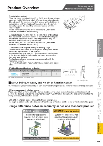
Installation method
When the upper plate is slid to CW or CCW side, 2 counterbored
holes are visible (4 holes in total). When a sine motion stage is
driven through the controller, the limit sensor works, but there is
no guarantee for the detection of mounting holes. Be sure to
manually expose the mounting holes and secure with the
supplied bolts.
Please pay attention to the above instructions. [Reference
standard of flatness: 10μm or less]
About objects mounted on the top / bottom of the stage
If an object with an uneven surface is mounted or the stage is
mounted on an uneven surface, the stage surface may be
deformed and accuracy may be affected. 9
Please pay attention to the above instructions. [Reference
standard of flatness: 10μm or less]
About installation posture of positioning stage
The horizontal installation of the stage is a prerequisite for the Screws / Positioning Stages Locating Pins / Bushings / Clamping
performance parameters of each product.
Be careful when using a product that is mounted upside down,
to the side (vertically or horizontally), or in any posture other
than on a level surface.
The load capacity and accuracy may vary greatly with the
installation posture. Pins Locating
For Product Features by Posture information, pleas refer to below
table:
P.745
▼Table of Product Features by Posture
Part Number Movable guide (feeding method) Upside-down use Side (horizontal) use Side (vertical) use
E-GMPG Cross roller G G G Locating Pins Bushings for
E-GMPWG (ball screw) Upside-down mounting
O Usable, with restrictions on load and torque. P.749
Side (vertical) mounting
QAbout Swing Accuracy and Height of Rotation Center Bolts Adjusting
Our cross roller type goniometer stages have a very small swing around the center of rotation and high accuracy.
P.753
Swing accuracy of rotation center
Place a steel ball at the height of the center of rotation (the actual center of rotation, not the theoretical
point in the design), and use the amount of swing (X.Y.Z) of the ball during the full stroke movement as the
swing accuracy of the rotation center. Screws Clamp
Height of rotation center (interval between workpieces) P.760
The height of rotation center is the distance between the top of the stage and the center of the steel ball of the guide.
Usage difference between economy series and standard product Pushers Urethane
MISUMI standard product MISUMI Economy series P.763
Suitable for applications Suitable for applications not
requiring high precision such requiring high precision such Heads Micrometer
as precise adjustment as simple adjustment
P.767
Motorized
Positioning Stages
P.769
Equipment name: Workpiece Assembly Posture Fine-Adjustment Device Equipment name: Motor Installation Error Simulation Testing Machine
808
1BSU @&/ JOEC
1BSU @&/ JOEC