
Page 105 - MISUMI Thailand Economy Series
P. 105
Format Series Price Ratio Shipping Search Drawing Product Material Table Techinfo Others BD M D GM Format Series Price Ratio Shipping Search Drawing Product Material Table Techinfo Others BD M D GM
Title
Pict
KW
Title
Pict
KW
Name
Date
Name
Date
AK AK
M M
1 1
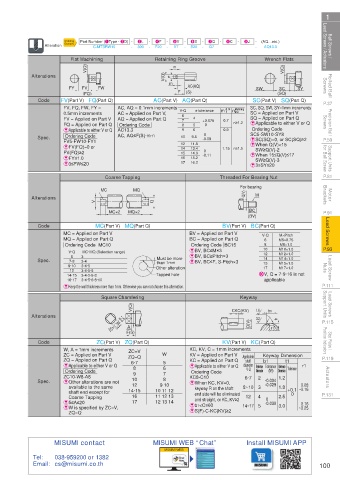
Ball Screws / Lead Screws / Actuators Alteration Ordering Part Number (1Type · 2D) - - 3L - - F20 - - 5V - - 6S - - 7Q - 8C - 9J - - (AQ…etc.) Lead Screws / Actuators Ball Screws /
4F
Example
300
Q7
V7
S20
C-MTSRW10
AQ13.3
Flat Machining
Wrench Flats
Retaining Ring Groove
Rolled Ball Screws Alterations FY FV V(Q) FW V(Q) m e n F (S) SW (SQ) V(Q) SY Screws Rolled Ball
AC(AQ)
SC
(FQ)
SC(Part V) SQ(Part Q)
AC(Part V) AQ(Part Q)
P.37 Code FV(Part V) FQ(Part Q) AC, AQ = 0.1mm increments V·Q e tolerance m 0 +0.14 n limit SC, SQ, SW, SY=1mm increments P.37
FV, FQ, FW, FY =
Machining
Precision Ball Screws 0.5mm increments AC = Applied on Part V, 6 7 8 9 4 5 6 +0.075 0.7 n≥1.2 SQ = Applied on Part Q Screws Precision Ball
SC = Applied on Part V
FV = Applied on Part V
AQ = Applied on Part Q
E Applicable to either V or Q
Ordering Code
FQ = Applied on Part Q
0
Ordering Code
AC13.3
EApplicable to either V or Q
0.9
Ordering Code
9.6
ESC(SQ)=0, or SC(SQ)≥2
-0.09
P.59 Spec. FV5-FW10-FY1 AC, AQ≤F(S)-m-n 10 11.5 0 1.15 n≥1.5 SC5-SW10-SY8 P.59
E When Q(V)<15
12
Support Units for Ball Screw FV(FQ)≥2 15 14.3 0 E When 15≤Q(V)≤17 for Ball Screw Support Units
EFV(FQ)=0 or
13.4
14
SW≥Q(V)-2
-0.11
EFY≤1.0
15.2
16
SW≥Q(V)-3
17
16.2
E3≤FW≤20
E3≤SY≤20
P.81 Coarse Tapping Threaded For Bearing Nut P.81
Motor Brackets Alterations V MC MQ Q For bearing nut Brackets Motor
Q(V)
M
BC
P.91 MC×2 MQ×2 (BV) P.91
Lead Screws Code MC = Applied on Part V BV = Applied on Part V V·Q M6×0.75 Lead Screws
BV(Part V) BC(Part Q)
MC(Part V) MQ(Part Q)
M×Pitch
BC = Applied on Part Q
MQ = Applied on Part Q
6
Ordering Code BC15
M8×1.0
8
P.93 Ordering Code MC10 Must be more EBV, BC≤M×3 10 M10×1.0 P.93
MC·MQ (Selection range)
V·Q
M12×1.0
12
EBV, BC≥Pitch×3
Lead Screw Nuts Spec. 14·15 3·4 Other alteration EBV, BC≤F, S-Pitch×3 X V, Q = 7·9·16 is not Nuts Lead Screw
6
3
M14×1.0
14
7·8
than 1mm
15
M15×1.0
3·4·5
9·10
17
M17×1.0
12
3·4·5·6
Tapped hole
3·4·5·6·8
16·17
3·4·5·6·8·10
P.111 E Keep the wall thickness more than 1mm. Otherwise you can not choose this alternation. applicable P.111
Lead Screws Support Units Square Chamfering CKC(KV) 1.6 b1 Support Units Lead Screws
Keyway
V(Q)
-0.1
P.115 Alterations 3.2 #W -0.3 A Q(V) 3.2 r1 t1 P.115
F(S)
Stop Plates / Position Indicators Code ZC(Part V) ZQ(Part Q) KV(Part V) KC(Part Q) Position Indicators Stop Plates /
ZC=V
KV = Applied on Part V
ZC = Applied on Part V
Applicable
P.119 W, A = 1mm increments ZQ=Q W KC, KV, C = 1mm increments Keyway Dimension P.119
ZQ = Applied on Part Q
KC = Applied on Part Q
shaft
b1
t1
EApplicable to either V or Q 6·7 5 6 E Applicable to either V or Q diameter Reference Tolerance Reference Tolerance r1
8
V·Q
Actuators Spec. ZC10-W8-A8 10 7 8 KC8-C10 6·7 2 -0.004 1.2 Actuators
Dimension
(N9)
Dimension
Ordering Code
Ordering Code
9
E Other alterations are not
E When KC, KV=0,
-0.029
0.08
9 10
12
available to the same
shaft end except for 14·15 10 11 12 keyway R on the shaft 8~10 3 1.8 +0.1 ~0.16
P.131 16 11 12 13 end side will be eliminated 0 P.131
Coarse Tapping and straight, or KC, KV≥2 12 4 0 2.5
E5≤A≤20 17 12 13 14 -0.030 0.16
E W is specified by ZC=V, Eb1<C≤60 14~17 5 3.0 ~0.25
ZQ=Q ES(F)-C-KC(KV)≥2
MISUMI contact MISUMI WEB “Chat” Install MISUMI APP
MISUMI WEB
Tel: 038-959200 or 1382
Email: cs@misumi.co.th 100
110310434339
1BSU @&/ JOEC
1BSU @&/ JOEC