
Page 102 - MISUMI Thailand Economy Series
P. 102
BD
Table
GM
Series
Product
Shipping
Search
Others
Format Series Price Ratio Shipping Search Drawing Product Material Table Title Techinfo Others BD M M D D GM Format Series Price Ratio Shipping Search Drawing Product Material Table Techinfo Others BD M D GM
Format
Drawing
Price Ratio
Techinfo
Material
Pict
Title
KW
Title
KW
Pict
Name
Name
Date
Name
Date
Pict
KW
Date
AK
AK AK
M M M
1 Economy series Alteration Options 1
Lead Screws
Ball Screws / Lead Screws / Actuators QAlteration Options Lead Screws / Actuators Ball Screws /
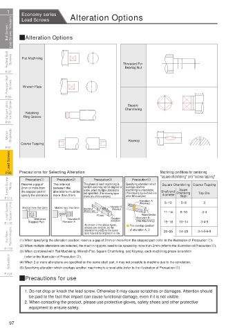
Rolled Ball Screws Flat Machining Threaded For Screws Rolled Ball
P.37 Bearing Nut P.37
Precision Ball Screws Wrench Flats Screws Precision Ball
P.59 P.59
Support Units for Ball Screw Retaining Chamfering for Ball Screw Support Units
Square
P.81 Ring Groove P.81
Motor Brackets Brackets Motor
Coarse Tapping Keyway
P.91 P.91
Lead Screws Lead Screws
P.93 Precautions for Selecting Alteration Machining conditions for combining P.93
"square chamfering" and "coarse tapping"
Lead Screw Nuts Reserve a gap of The interval The phase of each machining is Specifying alteration which Shaft end Square Coarse Tapping Nuts Lead Screw
Precaution2
Precaution4
Precaution3
Precaution1
Square Chamfering
random and may not be aligned in
overlaps another
between the
2mm or more from
machining is unavailable.
a row ,when multiple alterations
the stepped part to
alterations must be
of the NG examples)
Width
shows one of the examples)
P.111 specify the alteration more than 2mm are specified. (The following figure (The following figure shows one diameter Chamfering Tap Dia. P.111
Alteration A
6~10
3
5~8
Lead Screws Support Units Must be more than 2mm Must be more than 2mm Alteration A Phase Alteration B Rotation direction 11~14 8~10 3·4 Support Units Lead Screws
(Keyway)
(Keyway)
(Wrench Flats)
Alteration B
Rotation
Alteration B
Alteration
direction
(Flat Machining)
P.115 Stepped Part Alteration A As shown in the above figure, The overlap position 15~19 10~14 3·4·5 P.115
phases are random, so the
of alteration A, B
alteration A and B on the same
Stop Plates / Position Indicators (1) When specifying the alteration position, reserve a gap of 2mm or more from the stepped part (refer to the illustration of Precaution 1). Position Indicators Stop Plates /
14~20
20~25
3·4·5·6·8
axis may not be aligned in a row.
P.119 (2) When multiple alterations are selected, the machining parts need to be spaced by more than 2mm (refer to the illustration of Precaution 2). P.119
(3) When combined with Flat Machining, Wrench Flat, Square Chamfering, and Keyway, each machining phase is random
Actuators (4) When 2 or more alterations are specified on the same shaft part, it may not possible to machine due to the correlation. Actuators
(refer to the illustration of Precaution 3).
(5) Specifying alteration which overlaps another machining is unavailable (refer to the illustration of Precaution 4).
P.131 P.131
QPrecautions for use
1. Do not drop or knock the lead screw. Otherwise it may cause scratches or damages. Attention should
be paid to the fact that impact can cause functional damage, even if it is not visible.
2. When contacting the product, please use protective gloves, safety shoes and other protective
equipment to ensure safety.
97
1BSU @&/ JOEC
1BSU @&/ JOEC