Page 1596 - MISUMI Thailand Economy Series
P. 1596

[Technical Data]
                     Selection of Ball Screws 2


                   4. Allowable Axial Load                                                                                5. Allowable Rotational Speed
                   Allowable Axial Load is a load with a safety margin built-in against a shaft bucking load.             Ball screw rotational speed is determined by required feed speed and the given screw lead, and needs to be less than the Allowable Maximum Rotational Speed.
                   Axial load that applies to a ball screw needs to be less than Allowable Maximum Axial Load.            Ball screw rotational speed is evaluated based on the shaft's critical speed and ball recirculation speed limitation DmN value.
                   Allowable Axial Load can be obtained by the following formula.
                   Additionally, approximate Allowable Axial Load can be obtained from Table 1. Allowable Axial Load Graph.  5-1. Critical Speed
                                                                                                                          Allowable rotational speed is defined as a speed 80% or less of the Critical Speed where the rotational speed coincides with a natural resonant frequency of the screw shaft.
                   •Allowable Axial Load (P)                                                                              The Allowable Rotational Speed can be obtained by the following formula.
                                                                                                                          Additionally, approximate Allowable Rotational Speeds can be obtained from Table 2. Allowable Maximum Rotational Speed Graph.
                        n Q EI      d 4                        Allowable Axial Load Calculation Example
                          2
                                         4
                    P=     2  α=m    2 × 10 (N)                Find the Allowable Axial Load for Fig.1                    •Allowable Rotational Speed (rpm)
                         R         R
                    Where:                                     <How to use>
                    P: Allowable Axial Load (N)                · Thread shaft diameter  F15, Lead 5
                    ℓ: Distance between Points of Buckling Load (mm)  · Mounting method Fixed - Support
                                    5
                    E: Young's Modulus (2.06×10 N/mm ) 2       · Distance between Points of Buckling Load ℓ1  820mm
                     I: Min. Geometrical Moment of Inertia of Across Root Thread Area (mm ) 4  · Screw Shaft Root Diameter d  12.5
                          Q                                    <Calculations>
                       I=        d  4
                          64                                   m=10 since the mounting method is Fixed-Supported,
                    d :  Thread Root Diameter (mm)             the Allowable Axial Load(P) is,
                    n,m  :  Coefficient Determined by Method of Screw Support  d 4  12.5 4
                                                               P=m  M10 4 =10×  M10 4 =3630(N)
                          Method of Screw Support  n  m           R 2       820 2
                          Support - Support  1  5              Therefore, the allowable axial load will need to be 3630N or less.
                          Fixed - Support  2  10
                           Fixed - Fixed  4  19.9              Table.1
                           Fixed- Free  0.25  1.2
                     :  Safety Factor = 0.5
                      For higher safety, a higher safety factor should be required.
                                                                          Distance between Load Acting Points(Buckling Load:Fixed-Fixed) ℓ1
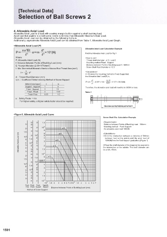
                   •Figure1. Allowable Axial Load Curve                                                                   •Figure2. Allowable Rotational Speed Graph
                                                                          Screw Shaft Dia. Calculation Example
                             6  3   1.5                                   <Requirements>
                          3  5                                            ·Distance between Points of Buckling Load 500mm
                          2  4  2   10 5 8      ø32                       ·Mounting method Fixed-Support
                                                                          ·the allowable axial load 10000N
                         1.5 4  3 2  1.5 5  6 5  ø25                      <Calculations>
                      Allowable Axial Load (N)  8 6 5 4  1.5 8 5  8 6 5 4  4 3 2  ø15 ø20  ②Read the shaft diameter of the diagonal line nearest to
                                10
                                                                          ①Find the intersection between a distance of 500mm
                         10
                                                                           between load acting points and the axial load of
                                                                           10000N(from the fixed-support graduation).[Figure 1]
                            10
                                                                          the intersection on the outside. The shaft diameter can
                          3
                             4 6 5  3 2  10 1.5 4                         be a min. 15mm.
                          2             ø10
                             3  1.5  8
                         1.5         6
                             2  10 4  10000N
                         10  3  8    4
                          8  1.5  6  3
                          6  10  4  5
                          5  8  4    2
                          4  6  3   1.5
                          3  5
                             4  2   10 3
                                      10  2  1.5  2  3  4  5  6  7  8  9 10 3  1.5  2  3  4  5  6  7
                          Fixed-  Fixed-  Fixed-  Support -
                          Free  Fixed  Support  Support  Distance between Points of Buckling Load (mm)
                           Method of Screw Support
                                                                                                                          5-2. DmN Value
                                                                                                                          The DmN value represents a ball recirculation (orbit) speed limit within a ball nut.
                                                                                                                          If this vale is exceeded, the recirculation components will be damaged.
                                                                                                                          •Allowable Rotational Speed (rpm)


            1591                                                                                                                                                                                                  1592


            KJTIV JOEC

            KJTIV JOEC
   1591   1592   1593   1594   1595   1596   1597   1598   1599   1600   1601