
Page 1598 - MISUMI Thailand Economy Series
P. 1598
[Technical Data]
Selection of Ball Screws 3
6. Life Span 7. Screw Shaft Mounting Arrangements
Ball screw's life is defined as: Total number of rotations, time, or distance where either the ball rolling surfaces or the balls begin to exhibit Representative ball screw mounting arrangements are shown below.
repetitive stress caused flaking. Ball screw's life can be calculated based on Basic Dynamic Load Rating with the following formula.
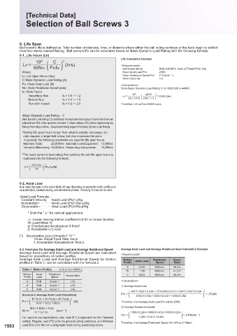
6-1. Life Hours (Lh) Mounting Methods Application Example
10 6 C 3 Life Calculation Example
Lh= ) (hrs) <Requirements>
60Nm ( Pmfw · Ball Screw Model BSS1520(Ø15 Lead 5(Thread Pitch 20))
Where: · Mean Axial Load Pm 250N · Typical method
Lh: Life Span Hours (hrs) · Mean Rotational Speed Nm 2118(min -1 ) · Medium ~ High Speeds
C: Basic Dynamic Load Rating (N) · Work Factor fw 1.2 · Medium ~High Accuracy
Pm: Mean Axial Load (N) <Calculations>
Nm: Mean Rotational Speed (rpm) Since Basic Dynamic Load Rating C for BSS1520 is 4400N,
fw: Work Factor
4400
Impactless Run fw = 1.0 ~ 1.2 Lh= 10 6 ( 250×1.2 ) 3 =24824(hr)
Normal Run fw = 1.2 ~ 1.5 60×2118
Run with Impact fw = 1.5 ~ 2.0 Therefore, Life will be 24824 hours.
· Medium Speeds
· High Accuracy
•Basic Dynamic Load Rating : C
Basic Dynamic Load Rating (C) is defined as: An axial load which a group of same ball screws are
subjected and 90% of the specimen will reach 1 million rotations (10 ) without experiencing any
6
flaking of the rolling surfaces. See product catalog pages for the Basic Dynamic Load Ratings.
* Setting life span hours longer than what is actually necessary not
only requires a larger ball screw, but also increases the price.
In general, the following standards are used for life span hours:
Machine Tools: 20,000hrs Automatic Control Equipment: 15,000hrs · Low Speeds
Industrial Machinery: 10,000hrs Measuring Instruments: 15,000hrs · For Short Screw Shafts
· Medium Accuracy
* The basic dynamic load rating that satisfies the set life span hours is
expressed by the following formula.
( 60LhNm ) 1 3
C= 10 6 Pmfw(N)
8. Temperature and Life
When ball screws are continuously used at 100°C or higher,
or used momentarily at very high temperatures, Basic
Dynamic/Static Load Ratings will be reduced according to the
6-2. Axial Load temperature rise due to changes in material compositions.
Axial loads that apply on the screw shafts will vary depending on applicable motion profile such However, there will be no effects up to 100°C. Basic Dynamic Load
as acceleration, constant velocity, and deceleration phases. Following formula can be used. Rating C" and Basic Static Load Rating Co" at 100°C or higher with the
-Axial Load Formula- temperature factors ft and ft' can be expressed with the following formula.
Constant Velocity· · ·Axial Load (Pb)=µWg
Acceleration· · · · · · ·Axial Load (Pa)=W +µWg
Deceleration· · · · · · Axial Load (Pc)=W -µWg
* Omit the "O" for vertical applications. Temperature °C 100 or less 125 150 175 200 225 250 350
O: Linear bearing friction coefficient (0.02 or Linear Guides) ft 1.0 0.95 0.90 0.85 0.75 0.65 0.60 0.50
W: Load Mass N ft' 1.0 0.93 0.85 0.78 0.65 0.52 0.46 0.35
g: Gravitational Acceleration 9.8m/s 2
: Acceleration (*) m/s2 E Normal usage range is -20 ~ 80℃ . For application in high
temperature, use of heat resistant grease as well as heat resistivity of
(*) Acceleration (α)=(Vmax/t)×10 -3 other components should be evaluated.
Vmax: Rapid Feed Rate mm/s
t: Acceleration/Deceleration Time s
6-3. Formulas for Average Axial Load and Average Rotational Speed Average Axial Load and Average Rotational Seed Calculation Example
Average Axial Load and Average Rotational Speed are calculated
based on proportions of motion profiles. <Requirements>
Average Axial Load and Average Rotational Speed for Motion Motion Axial Load Rotational Hours
profiles in Table 1. can be calculated with the formula 2. Profile Speed Ratio
A 343N 1500min 29.4%
[Table 1. Motion Profile] (t1+t2+t3=100% )
B 10N 3000min 41.2%
Motion Axial Rotational Hours Ratio C 324N 1500min 29.4%
Profile Load Speed
A P1N N1min -1 t1% <Calculations>
B P2N N2min -1 t2% ① Average Axial Load
C P3N N3min -1 t3% 343 3 M1500M0.294+10 3 M3000M0.412+324 3 1
M1500M0.294 3
Pm = = 250(N)
[Formula 2. Average Axial Load Calculation] ( )
1500M0.294+3000M0.412+1500M0.294
( )
P1 N1t1+P2 N2t2+P3 N3t3 3 1
3
3
3
Pm= (N) Therefore, the Average Axial Load Pm will be 250N.
N1t1+N2t2+N3t3
N1t1+N2t2+N3t3 ② Average Rotational Speed
Nm= (min -1 )
1500M0.294+3000M0.412+1500M0.294
t1+t2+t3 ( )
0.294+0.412+0.294
For machine tool applications, max. load (P1) is applicable for the “Heaviest Nm = = 2118(min -1 )
cutting”. Regular Load (P2) is for the general cutting conditions, and Minimum Therefore, the Average Rotational Speed Nm will be 2118rpm.
1593 Load (P3) is for the non-cutting rapid feeds during positioning moves. 1594
KJTIV JOEC
KJTIV JOEC