
Page 1602 - MISUMI Thailand Economy Series
P. 1602
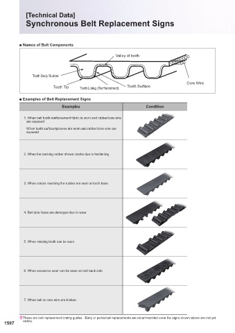
[Technical Data]
Synchronous Belt Replacement Signs
■ Names of Belt Components 1.Dimensions of the Rack for the Cutter and the Tolerances
Valley of teeth Pt
A A
Tooth Body Rubber a
Core Wire hr r2
Tooth Tip Tooth Lining (Reinforcement) Tooth Surface
b g r1
■ Examples of Belt Replacement Signs
Examples Condition Unit: mm
Number of Teeth of A hr bg 2a (1)
Type the Pulley Pt +0.05 +0.05 r1 r2
1. When belt tooth reinforcement fabric is worn and rubber/core wire Z Ú0.12 0 0 Ú0.03 Ú0.03 (Reference)
are exposed
10≤Z≤23 28B 0.61
When tooth surface/grooves are worn and rubber/core wire are MXL 24≤Z 2.032Ú0.008 20B 0.64 0.67 0.30 0.23 0.508
exposed
XL 10≤Z 5.080Ú0.010 25B 1.40 1.27 0.61 0.61 0.508
Note ( ) : a is a measurement indicating the position corresponding to the pitch line (Centerline of the Core Line of the Belt) of the belt corresponding to the
1
shape of the rack for the cutter.
2. Tolerance of Adjacent Pitch Error and Cumulative Pitch Error Unit: mm
2. When the backing rubber shows cracks due to hardening
Addendum Circle Diameter of Pulley Allowable Value
d0 Tolerance of Adjacent Pitch Error Accumulated Pitch Error
5.96≤d0≤ 25.40 0.03 0.05
25.40<d0≤ 50.80 0.03 0.08
50.80<d0≤101.60 0.03 0.10
101.60<d0≤177.80 0.05 0.13
3. When cracks reaching the rubber are seen at tooth base
177.80<d0≤304.80 0.05 0.15
304.80<d0≤508.00 0.08 0.18
508.00<d0≤762.00 0.08 0.20
762.00<d0≤967.16 0.08 0.23
4. Belt side faces are damaged due to wear 3. Tolerance of Side Deflection Unit: mm
Addendum Circle Diameter of Pulley Tolerance of Deflection(TIR) ( 2 )
d0
5.96≤d0≤101.60 0.10
101.60<d0≤254.00 Addendum Circle Dia. d0×0.001
5. When missing tooth can be seen 254.00<d0≤967.16 0.25+〔(Addendum Circle Dia. d0-254.00)×0.0005〕
Note ( ) : TIR is an abbreviation for Total Indicator Reading and
2
refers to the difference between the max. deflection
reading and the min.
deflection reading.
6. When excessive wear can be seen on belt back side
7. When belt or core wire are broken
E These are belt replacement timing guides. Early or periodical replacements are recommended even the signs shown above are not yet
1597 visible. 1598
KJTIV JOEC
KJTIV JOEC