
Page 1604 - MISUMI Thailand Economy Series
P. 1604
[Technical Data]
Designing of Chain Drive Mechanism 1
Selection of Power Transmission Efficiency Q Specification Selection for Operation under Normal Conditions
1.Operating Conditions
The table of transmission performance in this catalog (P.1602) is based on the following conditions. When selecting roller chains, the following 7
parameters should be taken into account.
Q Application Coefficient Table 1. Machine to be used 5. Diameter and Rotary Speed of High-Speed Shaft
1) The chain drive mechanism is run in an atmosphere with a The power transmission efficiency table (P.1602) is based on minimum
temperature of -10˚C~+60˚C and with no abrasive particles. 2. Impact Type 6. Diameter and Rotary Speed of Low-Speed Shaft
2) There is no adverse impact on the mechanism, load variation. The transmitted kW shown in the table should be 3. Prime Motor Type 7. Inter-Shaft Distance
such as corrosive gas or high humidity. corrected as follows depending on the actual magnitude of load variation. 4. Power Transmission(kW)
3) The two shafts between which power is
transmitted are parallel with each other and Table 1. Application Coefficient Table 2. Application Coefficient
correctly installed. Select the application coefficient from the application table(Table 1) that
4) The recommended lubrication method and oil are used. Impact Prime Motor Type Turbine Internal Combustion Engine is appropriate for the machine to be driven and the prime motor type.
5) The power transmission is subjected to Type Motor With Fluidic Without Fluidic
minimum load variation. Typical Mechanism Mechanism 3. Corrected Power Transmission(kW)
Correct the power transmission(kW)using the application
Belt conveyor with small load coefficient.
Smooth variation, Chain conveyor, • Single Chain…Corrected Power Transmission(kW)=Power
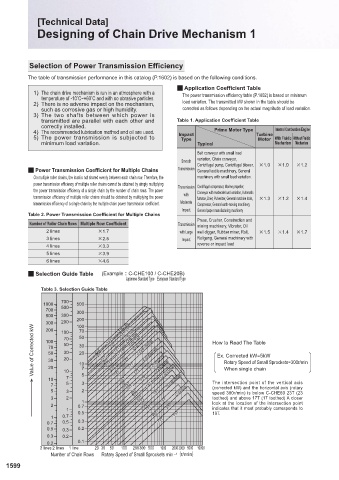
Q Power Transmission Coefficient for Multiple Chains Transmission Centrifugal pump, Centrifugal blower, ×1.0 ×1.0 ×1.2 Transmission(kW)×Application Coefficient
General textile machinery, General
On multiple roller chains, the load is not shared evenly between each chain row. Therefore, the machinery with small load variation. • Multiple Chains…Select the appropriate coefficient from the
power transmission efficiency of multiple roller chains cannot be obtained by simply multiplying Transmission Centrifugal compressor, Marine propeller, table multiple-chain power transmission coefficients(Table 2).
the power transmission efficiency of a single chain by the number of chain rows. The power Conveyor with moderate load variation, Automatic
transmission efficiency of multiple roller chains should be obtained by multiplying the power with furnace, Drier, Pulverizer, General machine tools, ×1.3 ×1.2 ×1.4
transmission efficiency of a single chain by the multiple chain power transmission coefficient. Moderate Compressor, General earth-moving machinery, 4. Chain and Number of Sprocket Teeth
Impact General paper manufacturing machinery Using the selection guide table(Table 3)or the power transmission
Table 2. Power Transmission Coefficient for Multiple Chains
Press, Crusher, Construction and efficiency tables, select the chain and the number of small sprocket teeth
Number of Roller Chain Rows Multiple Row Coefficient Transmission mining machinery, Vibrator, Oil that satisfy the rotary speed of the high-speed shaft and the corrected
2 lines ×1.7 with Large well digger, Rubber mixer, Roll, ×1.5 ×1.4 ×1.7 power transmission(kW). The chain pitch should be as small as possible,
3 lines ×2.5 Impact Rollgang, General machinery with as long as the required power transmission efficiency is achieved.
4 lines ×3.3 reverse or impact load This should minimize noise and ensure smooth transmission of power.
5 lines ×3.9 (If a single chain does not provide the required power transmission
6 lines ×4.6 efficiency, use multiple chains instead. If the installation space requires
that the inter-shaft distance as well as the outer diameter of sprocket be
Q Selection Guide Table (Example :C-CHE100 / C-CHE20B) minimized, use small-pitch multiple chains.)There should be a minimum
Japanese Standard Type European Standard Type wrap angle of 120˚ between the small sprocket and the chain.
Table 3. Selection Guide Table 5. Number of Large Sprocket Teeth
Number of Large Sprocket Teeth = Number of Small Sprocket
700 Teeth × Speed Ratio Once the number of small sprocket teeth is
1000 500 determined, multiplying this by the speed ratio provides the number
700 500 300
500 300 of large sprocket teeth. Generally, the appropriate number of small
300 200 200 CHE240 CHE180 sprocket teeth is 17 or greater, or 21 or greater for high-speed
100
operation, or 12 or greater for low speed operation. The number of
Value of Corrected kW 100 70 50 23T 29T 23T 23T 23T 19T 23T 19T 17T 17T CHE160 CHE120 C-CHE80/16B How to Read The Table 6. Shaft Diameter
CHE200
200
70
100
large sprocket teeth should be 120 or less.Select the sprocket with
CHE140
as great a number of teeth as possible for a speed ratio of 1:1 or 2:1.
C-CHE100/20B
50
30
The speed ratio should normally be 1:7 or less, and ideally 1:5.
70
30
50
20
Ex. Corrected kW=5kW
C-CHE60/12B
20
30
Ensure that the small sprocket selected as above is compatible with the diameter
Rotary Speed of Small Sprockets=300r/min
10
20
C-CHE40/09B
on this page. When the shaft diameter is too large for the bore in the sprocket,
10 10 7 7 5 23T 23T 23T 17T 17T 17T C-CHE50/10B C-CHE35/06B When single chain of the existing shaft on which it is to be installed. Refer to the specification table
select another sprocket with a greater number of teeth or a larger chain.
7 5 3 13T 23T 13T The intersection point of the vertical axis
(corrected kW) and the horizontal axis (rotary
5 3 2 23T 17T 13T C-CHE25 speed 300r/min) is below C-CHE60 23T (23 7. Inter-shaft Distance between Sprockets
3 2 1 23T 17T 13T toothed) and above 17T (17 toothed) A closer The distance between the shafts can be reduced as
2 0.7 23T 23T look at the location of the intersection point long as the sprockets do not interfere with each other
1 0.5 17T indicates that it most probably corresponds to and the wrap angle between the small sprocket and
1 0.7 30T 17T 13T 19T. the chain is 120˚ or more.
0.7 0.5 0.3 Generally, the inter-shaft distance should preferably
0.5 0.3 0.2 be 30~50 times the pitch of the chain used. Under
0.3 0.2 pulsating load conditions, decrease the distance to 20
0.2 0.1 times the chain pitch or less.
3 lines 2 lines 1 line 20 30 50 100 200 300 500 1000 20003000 5000 10000
Number of Chain Rows Rotary Speed of Small Sprockets min –1 {r/min}
1599 1600
KJTIV JOEC
KJTIV JOEC