
Page 1612 - MISUMI Thailand Economy Series
P. 1612
[Technical Data]
Designing of Chain Drive Mechanism 4
Selection procedure of No Crosspiece Type
Installation Way Horizontal Arrangement Lubrication
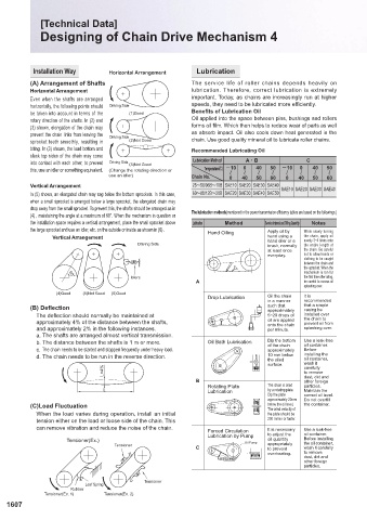
(A) Arrangement of Shafts The service life of roller chains depends heavily on [Step 1] Calculating the Effective Tension
Horizontal Arrangement lubrication. Therefore, correct lubrication is extremely
Even when the shafts are arranged important. Today, as chains are increasingly run at higher
horizontally, the following points should Driving Side speeds, they need to be lubricated more efficiently.
be taken into account in terms of the (1)Good Benefits of Lubrication Oil Formula 1 F=f(WG+W1+W2)L+f(W1+W3)L±WG · H
rotary direction of the shafts. In (2) and Oil applied into the space between pins, bushings and rollers
(3) shown, elongation of the chain may forms oil film. Which then helps to reduce wear of parts as well
prevent the chain links from leaving the Driving Side as absorb impact. Oil also cools down heat generated in the F : Effective Tension
f : Rolling friction coefficient of rollers, or friction coefficient
sprocket teeth smoothly, resulting in (2)Not Good chain. Use good quality mineral oil to lubricate roller chains. between belt and supports (Select from Table -1)
biting. In (3) shown, the load bottom and Recommended Lubricating Oil WG : Weight of Carried Materials per Meter of Belt kg/m
slack top sides of the chain may come W1 : Weight of belt per Meter kg/m
into contact with each other; to prevent Driving Side (3)Not Good Lubrication Method ACB C W2 : Carrier Roller Weight per 1m kg/m (Select from Table -2)
this, use an idler or something equivalent. (Change the rotating direction or Temperature (A) -10 0 40 50 -10 0 40 50 W3 : Return Roller Weight per 1m kg/m (Select from Table -2)
use an idler) Chain No. 0 ~ 40 ~ 50 ~ 60 ~ 0 ~ 40 ~ 50 ~ 60 ~ L : Conveyor Horizontal Length m
Vertical Arrangement 25~50/06B~10B SAE10 SAE20 SAE30 SAE40 SAE10 SAE20 SAE30 SAE40 H : Vertical Height (+Up angle, -Down angle) m
In (5) shown, an elongated chain may sag below the bottom sprockets. In this case, 60~80/12B~20B SAE20 SAE30 SAE40 SAE50
when a small sprocket is arranged below a large sprocket, the elongated chain may
drop away from the small sprocket. To prevent this, the shafts should be arranged as in The lubrication methods(mentioned in the power transmission efficiency tables are based on the followings.) Table of f Values(Table 1)
(4) , maintaining the angle at a maximum of 60°. When the mechanism in question or Belt Surface in Contact with Supports Smooth Cloth Surfaced
the installation space requires a vertical arrangement, place the small sprocket above Lubrication Method Service Interval and Oiling Quantity Notes
the large sprocket and use an idler, etc. on the outside or inside as shown in (6) . Hand Oiling Apply oil by While slowly turning Roller Support 0.05 0.05
Vertical Arrangement hand using a the chain, apply oil Roller+Steel Plate Support 0.2 0.3
evenly 3~4 times onto
Driving Side hand oiler or a the entire length of
brush, normally
at least once the chain. Be careful Steel Supported (SUS·SS) 0.4 0.5
everyday. not to allow hands or
clothing to be caught Plywood Support 0.5 0.6
between the chain and
the sprocket. When the (When knife edges are used, add 0.2 to the above values in Table -1.)
mechanism is run for
Idlers the first time after oiling, Carrier Side: As the back of the belt has a cloth
60°
A be careful to excess oil surface, avoid using iron plate or
splashing over. plywood as support as much as
(4)Good (5)Not Good (6)Good possible.
Drop Lubrication Oil the chain It is
in a manner recommended
(B) Deflection such that that a simple
casing be
approximately
The deflection should normally be maintained at 5~20 drops of installed over
approximately 4% of the distance between the shafts, oil are applied the chain to Return Side: When the front side of the belt has a cloth
prevent oil from
onto the chain
and approximately 2% in the following instances. per minute. splashing over. surface, or is coated with silicon or
fluorocarbon resin, avoid using iron plate or
a. The shafts are arranged almost vertical transmission. plywood as support as much as possible.
b. The distance between the shafts is 1 m or more. Oil Bath Lubrication Dip the bottom Use a leak-free (Some types of belts identified by specific
oil container.
of the chain
c. The chain needs to be started and stopped frequently under heavy load. approximately Before product names are compatible with the roller,
d. The chain needs to be run in the reverse direction. 10 mm below installing the Table of Roller Weight (Table 2) table.)
oil container,
the oiled
surface. wash it Roller Dia. (mm) Single Roller (kg/roller) Allowable Load (kg/roller)
L×4% carefully 28.6 0.2 50
to remove
B dust, dirt and Table-2 shows the weight of the revolving
other foreign
Rotating Plate The chain is oiled particles.
L Lubrication by a rotating plate. Maintain the parts of a roller that meets (JISB8805-1965).
Dip the plate correct oil level. For accurate calculation, check the actual
approximately 20mm Do not overfill
(C)Load Fluctuation below the oil level. the container. weight of the roller being used.
The wind velocity of
When the load varies during operation, install an initial the plate should be [Step 2] Power Requirement
tension either on the load or loose side of the chain. This 200 m/min or faster.
can remove vibration and reduce the noise of the chain.
Forced Circulation It is necessary Use a leak-free
Lubrication by Pump to adjust the oil container.
Tensioner(Ex.) Oil Pump oil quantity Before installing
Tensioner C appropriately the oil container, [Step 3] Motor Power
wash it carefully
to prevent
overheating. to remove
dust, dirt and
other foreign
particles.
Tensioner
Leaf Spring
Rubber
Tensioner(Ex. 1) Tensioner(Ex. 2)
1607 1608
KJTIV JOEC
KJTIV JOEC