
Page 1613 - MISUMI Thailand Economy Series
P. 1613
[Technical Data] [Technical Data]
Designing of Chain Drive Mechanism 4 Selection of Flat Belts
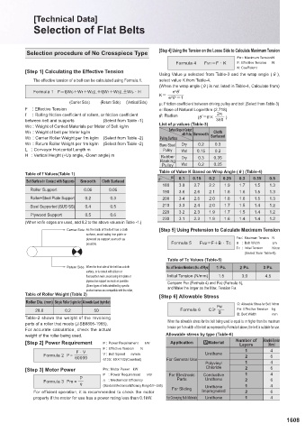
Selection procedure of No Crosspiece Type [Step 4] Using the Tension on the Loose Side to Calculate Maximum Tension
FM1: Maximum Tension N
Formula 4 FM1=F · K F: Effective Tension N
The service life of roller chains depends heavily on [Step 1] Calculating the Effective Tension K: Coefficient
lubrication. Therefore, correct lubrication is extremely Using Value μ selected from Table-3 and the wrap angle ( ),
important. Today, as chains are increasingly run at higher The effective tension of a belt can be calculated using Formula 1. select value K from Table-4.
speeds, they need to be lubricated more efficiently. (When the wrap angle ( ) is not listed in Table-4, Calculate from)
Benefits of Lubrication Oil Formula 1 F=f(WG+W1+W2)L+f(W1+W3)L±WG · H e F'
μ
K=
Oil applied into the space between pins, bushings and rollers e F ' -1
μ
forms oil film. Which then helps to reduce wear of parts as well (Carrier Side) (Return Side) (Vertical Side) μ: Friction coefficient between driving pulley and belt (Select from Table-3)
as absorb impact. Oil also cools down heat generated in the F : Effective Tension e: Base of Natural Logarithm (2.718)
chain. Use good quality mineral oil to lubricate roller chains. f : Rolling friction coefficient of rollers, or friction coefficient ': Radian 2π
(F′=F× )
between belt and supports (Select from Table -1) 360
Recommended Lubricating Oil WG : Weight of Carried Materials per Meter of Belt kg/m List of μ values (Table-3)
Cloth
Lubrication Method ACB C W1 : Weight of belt per Meter kg/m Surface Shape in Contact Surfaced
with Pulley Smooth
Temperature (A) -10 0 40 50 -10 0 40 50 W2 : Carrier Roller Weight per 1m kg/m (Select from Table -2) Pulley Surface
0.2
Dry
Chain No. 0 ~ 40 ~ 50 ~ 60 ~ 0 ~ 40 ~ 50 ~ 60 ~ W3 : Return Roller Weight per 1m kg/m (Select from Table -2) Bare Steel Wet 0.15 0.3
L : Conveyor Horizontal Length m
Pulley
0.2
25~50/06B~10B SAE10 SAE20 SAE30 SAE40 SAE10 SAE20 SAE30 SAE40 H : Vertical Height (+Up angle, -Down angle) m Rubber Dry
60~80/12B~20B SAE20 SAE30 SAE40 SAE50 Ranking 0.3 0.35
Pulley Wet 0.2 0.25
Table of Value K Based on Wrap Angle ( ) (Table-4)
Table of f Values(Table 1)
The lubrication methods(mentioned in the power transmission efficiency tables are based on the followings.) μ 0.1 0.15 0.2 0.25 0.3 0.35 0.5
Belt Surface in Contact with Supports Smooth Cloth Surfaced F°
Lubrication Method Service Interval and Oiling Quantity Notes Roller Support 180 3.8 2.7 2.2 1.9 1.7 1.5 1.3
Hand Oiling Apply oil by While slowly turning 0.05 0.05 190 3.6 2.6 2.1 1.8 1.6 1.5 1.3
hand using a the chain, apply oil Roller+Steel Plate Support 0.2 0.3 200 3.4 2.5 2.0 1.8 1.6 1.5 1.3
hand oiler or a evenly 3~4 times onto
brush, normally the entire length of 210 3.3 2.4 2.0 1.7 1.5 1.4 1.2
at least once the chain. Be careful Steel Supported (SUS·SS) 0.4 0.5
everyday. not to allow hands or 220 3.2 2.3 1.9 1.7 1.5 1.4 1.2
clothing to be caught Plywood Support 0.5 0.6
between the chain and 230 3.1 2.3 1.9 1.6 1.4 1.4 1.2
the sprocket. When the (When knife edges are used, add 0.2 to the above values in Table -1.)
mechanism is run for
the first time after oiling, Carrier Side: As the back of the belt has a cloth [Step 5] Using Pretension to Calculate Maximum Tension
A be careful to excess oil surface, avoid using iron plate or
splashing over. plywood as support as much as FM2: Maximum Tension N
possible. Formula 5 FM2=F+B · TC B : Belt Width cm
Drop Lubrication Oil the chain It is TC : Initial Tension N/cm
in a manner recommended
such that that a simple (Select from Table-5)
approximately casing be Table of Tc Values (Table-5)
5~20 drops of installed over
oil are applied the chain to Return Side: When the front side of the belt has a cloth No. of Tension Members (No. of Plys) 1 Pc. 2 Pc. 3 Pc.
onto the chain prevent oil from surface, or is coated with silicon or
per minute. splashing over. fluorocarbon resin, avoid using iron plate or Initial Tension (N/mm) 1.5 3.0 4.5
plywood as support as much as possible.
Oil Bath Lubrication Dip the bottom Use a leak-free (Some types of belts identified by specific Compare FM1 (Formula 4) and FM2 (Formula 5),
of the chain oil container. and Make the larger as the Max. Tension FM.
approximately Before product names are compatible with the roller,
10 mm below installing the Table of Roller Weight (Table 2) table.) [Step 6] Allowable Stress
the oiled oil container,
surface. wash it Roller Dia. (mm) Single Roller (kg/roller) Allowable Load (kg/roller) C: Allowable Stress for Belt N/mm
carefully FM
to remove 28.6 0.2 50 Formula 6 C≥ FM: Effective Tension kg
dust, dirt and B B: Belt Width mm
B other foreign Table-2 shows the weight of the revolving
Rotating Plate The chain is oiled particles. parts of a roller that meets (JISB8805-1965). When the allowable stress for the belt being used is equal to or higher than the maximum
Lubrication by a rotating plate. Maintain the tension per 1cm width of the belt as expressed by Formula 6 above, the belt is suitable for use.
Dip the plate correct oil level. For accurate calculation, check the actual
approximately 20mm Do not overfill Allowable stress by type (Table-6)
below the oil level. the container. weight of the roller being used.
The wind velocity of [Step 2] Power Requirement Application MMaterial Number of Allowable Tension
the plate should be P : Power Requirement kW Layers (N/mm)
200 m/min or faster. F : Effective Tension N
F ∙ V V : Belt Speed m/min Urethane 1 4
60000
Forced Circulation It is necessary Use a leak-free Formula 2 P = 6120: 60×102(Constant) For General Use 2 6
Lubrication by Pump to adjust the oil container. Polyvinyl 1 4
oil quantity Before installing Chloride
appropriately the oil container, [Step 3] Motor Power Pm: Motor Power kW 2 6
C to prevent wash it carefully P : Power Requirement kW For Electronic Conductive 1 4
overheating. to remove P Parts Urethane
dust, dirt and Formula 3 Pm = J : Mechanical Efficiency 2 6
other foreign (Standard Mechanical Efficiency Range0.5~0.65) 1 4
particles. For Sliding Urethane
For efficient operation, it is recommended to check the motor Impregnated 2 6
property if the motor for use has a power rating less than 0.1kW. For Conveying Bulk Materials Urethane 1 4
1607 1608
KJTIV JOEC
KJTIV JOEC