
Page 1615 - MISUMI Thailand Economy Series
P. 1615
[Technical Calculation] [Technical Calculation]
Calculation method and the concept of basic rating life of the ball bearing Excerpted from GB/T 6391—2010 Dimension of Normal Parallel Key Type Excerpted from GB/T 1096—1979
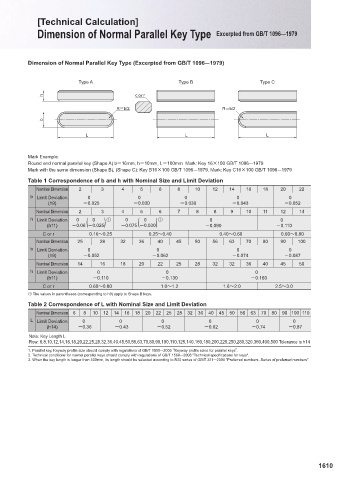
1. ■ Life Dimension of Normal Parallel Key Type (Excerpted from GB/T 1096—1979)
Life (of a single set of rolling bearings) refers to the number of revolutions that one collar or washer of a bearing rotates relative to an-
other collar or washer before the first sign of fatigue expansion appears on one collar or washer or rolling element material of the
bearing. Type A Type B Type C
Note: Life can also be expressed in hours of operation at a given constant speed.
h c or r
2. ■ Basic rating life
For bearings with currently used common high-quality materials, good processing quality and operating under normal operating condi- R=b/2 R=b/2
tions, it refers to the rated life related to 90% reliability. b
3. ■ Modified rating life L L L
The rating life obtained by modifying the basic rating life considering 90% or other reliability levels, bearing fatigue loads and/or spe-
cial bearing performance and/or contaminated lubricants and/or other unconventional operating conditions.
Mark Example:
4. ■ Basic dynamic radial load rating Round end normal parallel key (Shape A) b=16mm, h=10mm, L=100mm Mark: Key 16×100 GB/T 1096—1979
It refers to the constant radial load that a set of rolling bearings can bear theoretically. The basic rated life of the bearing under this Mark with the same dimension (Shape B), (Shape C): Key B16×100 GB/T 1096—1979, Mark: Key C16×100 GB/T 1096—1979
load is one million revolutions.
Note: For a single row angular contact bearing, the load refers to the radial component of the load that causes the bearing rings to Table 1 Correspondence of b and h with Nominal Size and Limit Deviation
produce pure radial displacement between each other. Nominal Dimension 2 3 4 5 6 8 10 12 14 16 18 20 22
b Limit Deviation 0 0 0 0 0
5. ■ Dynamic equivalent radial load (h9) -0.025 -0.030 -0.036 -0.043 -0.052
It refers to a constant radial load, under which the rolling bearing has the same life as that under the actual load condition. Nominal Dimension 2 3 4 5 6 7 8 8 9 10 11 12 14
h Limit Deviation 0 ( 0 ) ① 0 ( 0 ) ① 0 0
6. ■Dynamic equivalent radial load (h11) -0.06 -0.025 -0.075 -0.030 -0.090 -0.110
6.1 Dynamic equivalent radial load of single set of bearing C or r 0.16~0.25 0.25~0.40 0.40~0.60 0.60~0.80
The dynamic equivalent radial load of radial contact and angular contact ball bearings under constant radial and axial loads is: Nominal Dimension 25 28 32 36 40 45 50 56 63 70 80 90 100
Pr =XFr + YFa EEEEEEEEEEEEEEEEEEEEEEEEEEEEE (3) b Limit Deviation 0 0 0 0
See Table 1 on P.649 for X and Y values. These coefficients are applicable to bearings with raceway groove curvature radius comply- (h9) -0.052 -0.062 -0.074 -0.087
ing with requirements listed on P.649. For the curvature radius of the other raceway grooves, the X and Y values can be calculated by
4.2 in ISO/TR 8646:1985. Nominal Dimension 14 16 18 20 22 25 28 32 32 36 40 45 50
h Limit Deviation 0 0 0
6.2. Dynamic equivalent radial load of bearing group (h11) -0.110 -0.130 -0.160
6.2.1 Single row angular contact ball bearing "back-to-back" or "face-to-face" configuration C or r 0.60~0.80 1.0~1.2 1.6~2.0 2.5~3.0
Two sets of identical single row angular contact ball bearings are installed side by side on the same shaft in "back-to-back" or "face- ① The values in parentheses (corresponding to h9) apply to Shape B keys.
to-face" configuration, and rotate as a whole (installed in pairs). When calculating their dynamic equivalent radial load, it should be
considered as a set of double row angular contact bearings. Table 2 Correspondence of L with Nominal Size and Limit Deviation
Note: If two sets of identical single row radial contact ball bearings operate in a "back-to-back" or "face-to-face" configuration, users Nominal Dimension 6 8 10 12 14 16 18 20 22 25 28 32 36 40 45 50 56 63 70 80 90 100 110
should consult the bearing manufacturer for the calculation method of their dynamic equivalent radial load. L Limit Deviation 0 0 0 0 0 0
(h14) -0.36 -0.43 -0.52 -0.62 -0.74 -0.87
7. ■Basic rating life
7.1 Life formula Note: Key Length L
Row: 6,8,10,12,14,16,18,20,22,25,28,32,36,40,45,50,56,63,70,80,90,100,110,125,140,160,180,200,220,250,280,320,360,400,500 Tolerance is h14
The basic rating life formula for radial ball bearings is:
3 1. Parallel key, Keyway profile size should comply with regulations of GB/T 1095—2003 “Keyway profile sizes for parallel keys”.
C r
L 10=( ) EEEEEEEEEEEEEEEEEEEEEEEEEEEEEEE (4) 2. Technical conditions for normal parallel keys should comply with regulations of GB/T 1568—2008 "Technical specifications for keys".
P r
3. When the key length is longer than 500mm, its length should be selected according to R20 series of GB/T 321—2005 "Preferred numbers -Series of preferred numbers".
The life formula is also applicable to the life estimation of a bearing group consisting of two or more sets of single row bearing group.
At this time, the rated load C r is calculated according to the whole bearing group, the equivalent load P r is calculated according to the
total load acting on the bearing group, and the X and Y values used are based on the requirements listed in 6.2.
7.2 Load limiting conditions of life formula
The life formula can give a satisfactory result in a wide range of bearing loads. However, excessive loads can produce harmful plastic
deformation at the point of contact between the ball and the groove. Therefore, when P r is greater than the smaller of C 0r or 0.5C r, the
user should consult the bearing manufacturer to determine the applicability of the life formula.
Too small load can cause other failure modes, which are not included in this standard.
1609 1610
KJTIV JOEC
KJTIV JOEC