
Page 1573 - MISUMI Thailand Economy Series
P. 1573
[Technical Data] [Technical Data]
Roughness Ranges by Various Processes Geometric Tolerance Indications Excerpts from JIS B0021(1984)
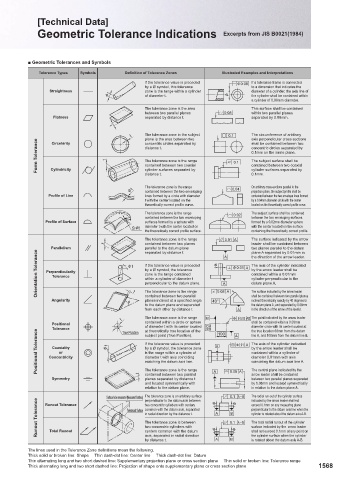
■ Geometric Tolerances and Symbols
100
Tolerance Types Symbols Definition of Tolerance Zones Illustrated Examples and Interpretations
400 If the tolerance value is preceded φ0.08 0.08
φ0.08 If a tolerance frame is connected
φ
φ0.08
φ0.08
-S by a Ø symbol, this tolerance φ0.08 φ
φ0.08 to a dimension that indicates the
φ
φ0.080.080.08
φ0.08
φ φ φ0.08
Straightness zone is the range within a cylinder φ φ0.08 φ
φ0.08
φ0.08 0.08 diameter of a cylinder, the axis line of
φ0.08
φ0.08
φ
φ0.08
φ t t t φ φ t φ of diameter t. φ φ φ φ0.080.08 the cylinder shall be contained within
φ0.08
φ0.08
φ0.080.08
φφ0.08
25 φ t φ φ t φ t φ t φ t φ t φ φ t t φ t φ t φ φ t t t φ t φ φ φ φ φ φ φ φ φ φ φ0.08 φ φ a cylinder of 0.08mm diameter.
φ
φ
φ0.08
φ0.08
φ0.08
φ t
φ0.08
φ φ0.08
φ
φ0.08
φ0.08 0.08
φ0.08 0.08
0.08 φ φ0.08
φ φ
φ0.08
φ
This surface shall be contained
0.08 φ φ
0.08 φ φ φ
φ
0.08 0.08 φ
within two parallel planes
between two parallel planes
0.08 φ
- φ t φ t φ t φ φ φ t φ t φ t φ φ t t t φ t φ t t φ t φ t The tolerance zone is the area 0.08 φ φ φ0.08 φ0.08
0.08 φ
0.08
0.08
Flatness φ t φ t φ t φ t φ t φ t t t φ t t φ t t separated by distance t. 0.08 φ 0.08φ 0.08 0.08 φ separated by 0.08mm.
0.08 φ
0.08 φ
0.08 φ
0.08
0.080.08
0.08
0.08
0.080.08
0.08
0.08
0.08
0.08
0.1
0.1 0.1 0.1
t t t t t t t t 0.08 0.08
0.08
t t t t t t t t t 0.08 0.08
0.08 0.08
0.1
0.1
0.08
t t t t t t t t t t t t t t t plane is the area between two 0.08 0.1 0.1 0.1 axis perpendicular cross sections
0.1
0.08 0.10.1
0.1
t t t t The tolerance zone in the subject 0.08 0.08 The circumference of arbitrary
0.08
0.1
t
t
0.1
0.1
t t
t t
0.1
Form Tolerance t t t t t t t t t t t t t t tt t t t t t t t t t t t t t t t t t t t t t t t t t t t distance t. 0.1 0.1 0.1 0.1 concentric circles separated by
t t
0.1
t t
t
0.1
0.1 0.1
shall be contained between two
concentric circles separated by
Circularity
t t t
0.1
0.1
t t t
0.1
0.1
t
0.1
t
0.1
0.1
0.1
0.1
0.1
0.1
0.1 0.1
0.1mm on the same plane.
0.1
0.1
0.1
0.1
0.1 0.1 0.1
0.1
0.1
The subject surface shall be
The tolerance zone is the range
0.1
0.1
0.1
0.1
0.1
0.1 0.1 0.1
0.1
contained between two coaxial
contained between two coaxial
0.1
0.1
Cylindricity
0.1 0.1
0.1
0.1
0.1
0.1
0.1 0.1
0.1mm.
distance t.
0.1
0.1
0.1
0.1
t t t t t t t t t t t t t t t t t cylinder surfaces separated by 0.1 0.1 0.1 cylinder surfaces separated by
tt 0.1
0.1 0.1
t t 0.1 0.04 0.1
0.1
0.1
0.1
0.04 0.04 0.1
0.04
φt t t φt φ φt The tolerance zone is the range 0.04 0.04 On arbitrary cross-sections parallel to the
φ
0.04
φt
0.04
0.04
0.04
0.04
0.04
φt φt
φt φt φt φt t φ φt φ φt t contained between the two enveloping 0.04 0.04 0.04 projection plane, the subject profile shall be
0.04
0.04
0.04
0.04
φt
φtφt
0.04
φt φ
0.04
Profile of Line φt φt φt φt t lines formed by a circle with diameter 0.040.04 contained between the two envelope lines formed
0.040.04
0.04
0.04
φt t
φt φt
φ
0.04
0.04
φ
t with the center located on the
φt t
by a 0.04mm diameter circle with the center
0.04
0.04
0.04
0.04
0.04
0.04 0.04
0.04
0.04
0.02
φt φ φtφ t φt φt φt t φt φt φt theoretically correct profile curve. 0.04 0.04 0.04 0.02 located on the theoretically correct profile curve.
0.02 0.02
0.02
0.02
0.02
0.02
0.02
0.02
0.02
0.02
The tolerance zone is the range 0.02 0.02 0.02 The subject surface shall be contained
0.02
0.02
0.02
S φ t S φ
S φ t t contained between the two enveloping
between the two enveloping surfaces
0.020.02
S φ
0.02
0.02
S φ ttt
0.020.02
Profile of Surface S φ S t S φφ 0.02 0.02 formed by a 0.02mm diameter sphere
S φ t φ t surfaces formed by a sphere with
0.02
S φ
0.02
0.02
S t φ t t
0.02
0.02
S S φ t S S S φ t 0.01 AA A 0.02 with the center located on the surface
0.02
0.02
S φ t φ t φ t diameter t with the center located on
0.01 A 0.02
0.01 0.01 0.02
0.02 0.02
0.02
S φ t φ t the theoretically correct profile surface.
0.01 A 0.02
0.01 A 0.02
S φ
S φ t t
S φ t S φ t φ t
0.01
0.01
t t t t S φ t S S φ t 0.01 A 0.01 AAA containing the theoretically correct profile.
S φ t S
0.01 A
S φ t
S φ
0.01 AA A
0.01 A
S t
0.01 A
S φ
t t t t t t S φ 0.01 0.01
0.01 A
0.01 A
S φ t φ t The tolerance zone is the range
0.01 A A
S φ t t φ t S φ t φ t
t t t t t S φ t S t 0.01 0.01 A The surface indicated by the arrow
0.01 A A
t t t t t t t S φ t S 0.01 0.01 leader shall be contained between
0.01 A A
S φ t S φ t contained between two planes
0.01 A0.01 A
0.01
A A A
A 0.01 A A
A 0.01
A 0.01 A
0.01 A
Parallelism t t t t t t t t t t t t t t t t t t t φt φt φt φt parallel to the datum plane φ φ φ φ A φφ A φ A 0.01 A φ0.01 A the direction of the arrow leader.
two planes parallel to the datum
0.01
A 0.01 A A
A 0.01 A
φ φφ A 0.01 A
A A A 0.01 A
φt
φ A 0.01 A
φt φt φt
0.01
Orientation Tolerance Tolerance φt φt φt φt t t t t t t t zone is the range contained 40° 0.08 A A0.08 A A φ0.01 A A datum plane A.
φ
separated by distance t.
plane A separated by 0.01mm in
φ AA A A 0.01 A
A
φ0.01 A
φt
φ0.01
φ0.01
φ0.01 AA A
φ
φt
φ
φ
A
Aφ0.01 A
φttt
φ
φt
φ
φ
A A φ0.01 A
φ0.01 AAA
φ0.010.01
φ0.01
A φ0.01 A
φ A A
φt
φ0.01 AA A
A φ0.01 A
φ
A
φ0.01
φt φt
φt
A
φ A
φ φ A φ0.01 A
φ0.01 A
φ A
φ
φ
φ0.01 A The axis of the cylinder indicated
φt φt
φ0.01 A A
A
A
φt
φt
φ0.01
φt φt
φ A A
φ0.01 A A
φ
φt
φt
A φ0.01
φ
φ φ A
by a Ø symbol, the tolerance
φt
A φ0.01 A
φ
AA A A φ0.01 A A
φ0.01 Aby the arrow leader shall be
φt
φ0.01 A
φt
φ
Coarse Perpendicularity φt φt φt If the tolerance value is preceded φ φ φ A A φ0.01 φ0.01 A
φ0.01 A
φt
φ0.01
φt
φ φ A
φ
φ0.01 A
φ
A A φ0.01 A A contained within a 0.01mm
φt
A A φ0.01 A
A
φ
0.08 0.08 φ
φ0.01
φ φ0.01 A
φt
0.08A
φt
φ0.01 A
t t t
0.08 A A A φ0.01
A AA φ0.01 A A
A
φ0.01 A cylinder perpendicular to the
A A φ0.01 A
within a cylinder of diameter t
0.08 A
0.08 A
0.08
0.08 A
A A A
A A
0.08 A 0.080.08 A
A
perpendicular to the datum plane.
0.08 A
0.08
0.08 A
AA A
t t t t
0.08
t t
40° A A A
40° 40°
A A
0.08
t
0.08 A A
40° 0.08
40° A A A0.08 A
40° A A A0.08
0.08A
40°A
40° A A
40° 0.08
The surface indicated by the arrow leader
40° 0.08
0.080.08
40°
40°
A
0.08 A
40° 0.08
0.08 A
shall be contained between two parallel planes
contained between two parallel
A A A
40° 40° A0.08
40°
40° 0.08A0.08 0.08
A
0.08
B 40° A0.08 0.08 A
A φ φ
φ0.03
A A
t t t t t t t t t planes inclined at a specified angle
Angularity t t t t t t t t t t t t t t t t t t t The tolerance zone is the range 40° 40° 40° A A0.08 A0.08 A A A A A A A A A A A A A A AA A φ0.03 0.03 0.03 AB AB
AB ABAB inclined theoretically exactly by 40 degrees to
40°
40°40° A0.08
B
B B 40° 0.08 A
40°
A φ
40°
B 40°
AB
B
φ0.03
AA A 0.03
40°
40°
Aφ0.03
φ φ AB
60 BB 40° BB
φ0.03 ABAB
AB
B 60 B 40°
φ AB
t t t t t t to the datum plane and separated B 40° B 60 40° 60B A A A φ A0.03 φ 0.030.03 the datum plane A, and separated by 0.08mm
B
A φ0.03 AB
AB AB AB
40° B 40°
A φ0.03
φ0.03 0.03 0.03 AB in the direction of the arrow of the leader.
A
φ0.03 AB
60 60
t t t t t t t from each other by distance t. 40° 60 B 40° A A Aφ0.03 AB
AB AB
AB
t t t t True Position 60 B B 60 B 60 B 40° 60 B 60 40° A A A A φ φ0.03 φ0.03 AB
A A φ0.03
φ0.03 φ0.03
φ0.03 AB
100 A A 0.03 AB
AB
t True Position
t True Position
φ0.03 φ0.03
AB AB
t
Aφ A
True Position The tolerance zone is the range
100 A
AB
t t t True Position B 60 B B 60 60B B B 60 60 B B 60 60 100 100 A A φ0.03 AB The point indicated by the arrow leader
100 A φ0.03
t True Position
A 0.03 AB
t
A
φ
A
AB
φ A 0.03 AB
100 A 0.03
t t True Position
True Position
60 B B 100
True Position
φ
60 B
True Position
100
100
AB
60
φ AB
Aφ0.03 AB AB
t True Position
True Position
100 100 A 0.03
φ0.03 0.03
100
φ0.01 A AB 0.03 shall be contained within a 0.03mm
A A A φ
φ
B 100
True Position contained within a circle or sphere
t True Position
B 100
True Position
t
A AB
True Position
AB
A 0.03
Positional t t t True Position B B 60 B 60 60 60 B 60 60 100 100 A φ0.03 φ0.01 φ0.03
AA A AB
A 0.03 φ0.01 AB
φ φ0.01 A
t
t
True Position
A 100
A
A 100
A A
True Position of diameter t with its center located
A diameter circle with its center located at
t
True Position
100100 φ A
60 100
A 0.01
Tolerance φ t φ t φ t φ tφ t φ t t t φ t φ t φ φ t φt φ t φ t φ t t φ t φ φ t φ t True Position 60 B 60 60 60 60 60 60 60 60 60 A A 100 A 100 φ A φ0.01 φ0.01 A A 0.01 AA A A A A the true location 60mm from the datum
True Position
True Position
φ φ AA
100
A φ0.01
A 100
A
A
φ0.010.010.01
True Position
A 100
True Position
60 100
A A
True PositionTrue Positionat theoretically true location of the
Positional Tolerance Concentricity φ t φ t φ t φ t φ t φ t φ φ t φ t φ t φ t φ t φ t t φ t φ φ t t φ t φ t φ t φ t φ t φ t φ t t t t t t t t t t t t t t t t t t t t If the tolerance value is preceded A A A A A AA A A A A 100 A 100 φ0.01 A A φ0.01A The axis of the cylinder indicated
A A A
100100 φ0.01
True Position
60
φ A φ A A
True Position
A
A 100
True Position
φ A
Aφ0.01
φ0.01 0.01 0.01 A
A 100
True Position
True Position
100
A A 100 A
A A 0.01
φ0.01 A
A line A, and 100mm from the datum line B.
True Position
True Position subject point (True Position).
100
True Position
A 100
True Position
φ0.01 φA
A A 100
A 0.01
A
A
True Position
True Position
A A
A
A A
100
A φ0.01
True Position
True Position
True Position
A A
100 100 φ0.01
A
A
φ0.01 φ A
A 0.01
φ0.01 A A
A A
A
φ0.01A A
φ0.01
A φ0.01
A A
φ0.01
φ0.01 A
A
A
A A
A
A
φ0.01 0.01
φ0.01
A A
φ A
A
φ
φ0.01
φ0.01 A
A
Coaxiality
A A
A 0.01
A
φ
by a Ø symbol, the tolerance zone
A φ0.01 by the arrow leader shall be
A
A A
A
0.08 0.01
A
A
AA A
A
0.08 0.08
0.08
or
is the range within a cylinder of
contained within a cylinder of
A
A
A
0.08 A
0.08
0.08
A
A A A
0.08
A A A
0.08
0.08
A
diameter t with axis coinciding
0.08 A
diameter 0.01mm with axis
0.08 A
AA A
AA A
0.08
A
0.08 0.08 A0.08
0.08 A
0.08
A
A
coinciding the datum axis line A.
matching the datum axis line.
A
0.08
0.080.08
A A
0.08
A A
0.08
A
0.08
t
t t
0.080.08
t t
0.08 A
0.08
0.08
A A
0.08 A
t t
0.08
A
t
The tolerance zone is the range
t
0.08A
0.08
0.08 0.08
t t t
Surface to be measured (Measured Surface)
Surface to be measured (Measured Surface)
0.1A
A-B AA-B A0.08
A-B
t t t
Surface to be measured (Measured Surface) contained between two parallel
arrow leader shall be contained
A 0.08
A
0.1 0.08 A-B0.1 0.1 0.08
t
Surface to be measured (Measured Surface) t
Surface to be measured (Measured Surface)
Surface to be measured (Measured Surface)
0.1 A-B
0.1
t tt
t
Surface to be measured (Measured Surface)
Surface to be measured (Measured Surface)
Surface to be measured (Measured Surface)
φ A-B
A-B
t t
φ 0.1 A-B0.1 A-B0.1
between two parallel planes separated
t
Symmetry Surface to be measured (Measured Surface) planes separated by distance t A A A A A A A A A A A A A A A A A 0.08 0.08 A A A φ A-B A A A A The central plane indicated by the
0.1
Surface to be measured (Measured Surface)
Surface to be measured (Measured Surface)
0.1
Surface to be measured (Measured Surface)
0.1 0.1 A-B
Surface to be measured (Measured Surface)
t t t
Surface to be measured (Measured Surface) φ φ φ φ φ φ 0.1 0.1 φ A-B φ A-B A-B by 0.08mm and located symmetrically
Surface to be measured (Measured Surface)
0.1
φ φ
A-B φ A-B0.1 A-B
t
0.1
B φ 0.1 φ A-B
Surface to be measured (Measured Surface)
Surface to be measured (Measured Surface) and located symmetrically with
φ A-B
Surface to be measured (Measured Surface)
Surface to be measured (Measured Surface)
t t
t t t
B 0.1 B φ 0.1B
B A-B φ A-B
Surface to be measured (Measured Surface)
Toleranced Surface
0.1φ
t Toleranced Surface
Toleranced Surface
t
Surface to be measured (Measured Surface)
0.1 φ
t
t
t
Surface to be measured (Measured Surface)
φ A-
φ 0.1
A-B
Surface to be measured (Measured Surface) φ φ φ φ A φ φ A φ φ A φ Aφ φ φA φ A φ φ A φ φ A φ A φ φ A φ φ φ AA φ A A φ A φ φ φ φ φ A A A 0.1 0.1 φ 0.1 φ A-B A-B A-B in relation to the datum plane A.
Toleranced Surface relation to the datum plane.
A-B
φ
Surface to be measured (Measured Surface)
t
Surface to be measured (Measured Surface)Surface to be measured (Measured Surface)
Toleranced Surface
A-B
0.1 φ 0.1 φ 0.1
φ A φ
Toleranced Surface
0.1
0.1 A-B
t t
B φ A-B
Surface to be measured (Measured Surface)
Surface to be measured (Measured Surface)
0.1
Toleranced Surface
Surface to be measured (Measured Surface)
t Toleranced SurfaceToleranced Surface
Toleranced Surface
0.1 φ BB φ A-B
t
φ 0.1 φ A-B A-B A-B0.1 B φ A-B
t t
Surface to be measured (Measured Surface)
A φ
Surface to be measured (Measured Surface)
0.1 φ A-B
t Toleranced Surface
Toleranced Surface
Toleranced Surface
B 0.1
B 0.1 A-B
Surface to be measured (Measured Surface)
Toleranced Surface
Surface to be measured (Measured Surface)
t
Toleranced Surface
B φ 0.1
Surface to be measured (Measured Surface)
B 0.1
0.1 0.1 B φ A-B
A-B
Surface to be measured (Measured Surface)
t Toleranced Surface
t
t
t
The radial run-out of the cylinder surface
Toleranced Surface The tolerance zone is an arbitrary surface
Surface to be measured (Measured Surface)
Surface to be measured (Measured Surface)
Toleranced Surface
A-B A-B
0.1φ A-B
B φ
B φ
BB 0.1
0.1
Surface to be measured (Measured Surface)
Surface to be measured (Measured Surface)
t t t
B 0.1φ A-B
Surface to be measured (Measured Surface)
Toleranced Surface
Toleranced Surface
0.1
A-B
Toleranced Surface
B φ B φ 0.1
t t
A-B
A
t Toleranced Surface
B
Toleranced Surface perpendicular to the datum axis between
Runout Tolerance Runout Tolerance Toleranced Surface in radial direction by the distance t. φ A φA φ φ A A φ A A φ φ φ A φ φ A A A φ 0.1 B φ 0.1φ B φ 0.1 φ A-B A-B A-B exceed 0.1mm on any measuring plane
indicated by the arrow leader shall not
A-B
t
t
φ A-B
Toleranced Surface
Toleranced SurfaceToleranced Surface
Toleranced Surface
A-B
B
t
φ φ 0.1 A-B
A-B-B
t
A
Toleranced Surface
φ A φ
φA A φ
B φ
t
Toleranced Surface
t
0.1 0.1 0.1 φ
Toleranced Surface two concentric cylinders with centers
Toleranced Surface
B φφ
A φ Aφ A φ
Toleranced Surface
A-B φA-B φ
0.1 B Bφ A-B0.1 A-B
φ 0.1 φ A-B
B B
B 0.1 B
Toleranced Surface
Toleranced Surface
Toleranced Surface
Toleranced Surface
φ A-B
0.1
φA-B
φ A
0.1
B
Toleranced Surface
φ A A
φ A
Toleranced Surface
perpendicular to the datum axis line when the
Toleranced Surface common with the datum axis, separated
B
B A-B φ A-B
0.1
B 0.1 B φ 0.1B
φ A-
Toleranced Surface
φ A
B
B 0.1 B
A-B
A-B
φ
φ 0.1 φB
cylinder is rotated about the datum axis A-B.
B
φ A φA
A-B
B φ 0.1 0.1 B
A φ A 0.1 A-B0.1
0.1 φ A-
B φ A-B
A A A B
A
B B 0.1 B
AA A B φ A-B0.1
0.1 φ
B φ BBφ A-B
0.1 φ A-B
B 0.1
BB φ A-B
B φ A-B0.1
A φ φ
φ A-Bφ A-B A-B
A-B
φ
B
φ A φ
φ φ A φ
B φ B φ 0.1
0.1
φ A-B
B
The total radial runout of the cylinder
B B φ A-B
0.1
The tolerance zone is between
B 0.1
A φ
A-B
φ
A φ A
A φ
A φ
A φ
φ
surface indicated by the arrow leader
two concentric cylinders with
B φ
A A φ
φ
φ
Total Runout
centers common with the datum
axis, separated in radial direction
the cylinder surface when the cylinder
by distance t. A A φ A A A A A A A A A A A A A A φ A A B B B B B B B B B φ B B B B B B B φ B B shall not exceed 0.1mm at any point on
is rotated about the datum axis A-B.
The lines used in the Tolerance Zone definitions mean the following.
Thick solid or broken line: Shape Thin dash-dot line: Center line Thick dash-dot line: Datum
Thin alternating long and two short dashed line: Supplementary projection plane or cross section plane Thin solid or broken line: Tolerance range
1567 Thick alternating long and two short dashed line: Projection of shape onto supplementary plane or cross section plane 1568
KJTIV JOEC
KJTIV JOEC