
Page 1575 - MISUMI Thailand Economy Series
P. 1575
[Technical Data] [Technical Data]
Basis of Fitting Selection/Dimensional Tolerances and Fitting
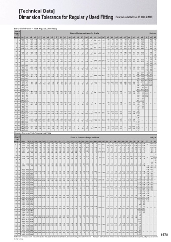
Drawing Manual in JIS (How To Use) Series Excerpted and edited from JIS B0401-1, -2 (1998) Dimension Tolerance for Regularly Used Fitting Excerpted and edited from JIS B0401-2 (1998)
Dimension Tolerance of Shaft, Regularly Used Fitting
H6 H7 H8 H9 Applicable Part Functional Classification Application Example Reference
Dimension Class of Tolerance Range for Shafts UnitOm
Part which accommodates a wide gap or moving part which needs a gap. Part whose structure needs a gap. (mm)
c9 Part which accommodates a wide gap to facilitate assembling. Inflates. Large position error Piston Ring and the Ring Groove More than or Less b9 c9 d8 d9 e7 e8 e9 f6 f7 f8 g5 g6 h5 h6 h7 h8 h9 js5 js6 js7 k5 k6 m5 m6 n5 * n6 p6 r6 s6 t6 u6 X6
Fitting by means of a loose set pin.
一6
Part which needs an appropriate gap even at a high temperature. { Fitting length is long. 一 3 一140 一60 一20 一20 一14 一14 一14 一12 一16 一20 一2 一2 一4 0 一6 0 一10 0 一14 0 一25 0 Ú2 Ú3 Ú5 +4 0 +6 0 +6 +8 +8 +10 +12 +16 +20 一 +24 +26
一6
一6
一28
一39
+4
一24
一8
一6
+2
+2
+18
一34
一45
+20
一165
一85
+4
+10
+6
+14
Cost needs to be reduced. Crank Web and Pin Bearing(Side) 一140 一70 一30 一30 一20 一20 一20 一10 一10 一10 一4 一4 0 0 0 0 0 +6 +9 +9 +12 +13 +16 +20 +23 +27 +31 +36
d9 d9 Part which accommodates or needs a gap. Manufacturing Cost Exhaust Valve Box and the Sliding Part of a Spring Bearing 3 6 一170 一100 一48 一60 一32 一38 一50 一18 一22 一28 一9 一12 一5 一8 一12 一18 一30 Ú2.5 Ú4 Ú6 +1 +1 +4 +4 +8 +8 +12 +15 +19 一 +23 +28
{ Maintenance Cost Piston Ring and the Ring Groove 6 10 一150 一80 一40 一40 一25 一25 一25 一13 一13 一13 一5 一5 0 0 0 0 0 Ú3 Ú4.5 Ú7.5 +7 +10 +12 +15 +16 +19 +24 +28 +32 一 +37 +43
Part which accommodates a wide gap or needs a gap. Fitting of the Exhaust Valve Box 一186 一116 一62 一76 一40 一47 一61 一22 一28 一35 一11 一14 一6 一9 一15 一22 一36 +1 +1 +6 +6 +10 +10 +15 +19 +23 +28 +34
+51
e7 e8 e9 Fairly wide gap, well greased bearing. Regular Rotary or Sliding Part Main Bearing for the Crank Shaft 10 14 一150 一95 一50 一50 一32 一32 一32 一16 一16 一16 一6 一6 0 0 0 0 0 Ú4 Ú5.5 Ú9 +9 +12 +15 +18 +20 +23 +29 +34 +39 +44 +40
Bearing subjected to a high temperature, high speed and heavy load(high-degree forced lubrication). (Must be well greased.) Regular Sliding Part 14 18 一193 一138 一77 一93 一50 一59 一75 一27 一34 一43 一14 一17 一8 一11 一18 一27 一43 +1 +1 +7 +7 +12 +12 +18 +23 +28 一 +33 +56
+45
f7 Fitting so as to provide an appropriate gap to permit movement(high-quality Regular Fitting Part in which a cooled exhaust valve box is inserted. 18 24 +54 +67
f6 f7 fitting). (Often comes apart.) Regular Shaft and Bushing 一160 一110 一65 一65 一40 一40 一40 一20 一20 一20 一7 一7 0 0 0 0 0 +11 +15 +17 +21 +24 +28 +35 +41 +48 一 +41 +54
f8 Ú4.5 Ú6.5 Ú10.5
Regular normal temperature bearing lubricated with grease or oil. Link Device Lever and Bushing 24 30 一212 一162 一98 一117 一61 一73 一92 一33 一41 一53 一16 一20 一9 一13 一21 一33 一52 +2 +2 +8 +8 +15 +15 +22 +28 +35 +54 +61 +77
+48
+64
+41
Continuously revolving part of a precision machine under a light load. Link Device Pin and Lever 一170 一120 +64 +76
g5 g6 Fitting with a narrow gap so as to permit movement(spigot and positioning). Part required to make a precision Key and its Groove 30 40 一232 一182 一80 一80 一50 一50 一50 一25 一25 一25 一9 一9 0 0 0 0 0 Ú5.5 Ú8 Ú12.5 +13 +18 +20 +25 +28 +33 +42 +50 +59 +48 +60
motion with virtually no play.
Precision sliding part. Precision Control Valve Rod 40 50 一180 一130 一119 一142 一75 一89 一112 一41 一50 一64 一20 一25 一11 一16 一25 一39 一62 +2 +2 +9 +9 +17 +17 +26 +34 +43 +70 +86 一
一242 一192
+54
+70
h7 Fitting so as to permit movement by hand, with a lubricant applied.(high-quality positioning) Fitting a rim and a boss together 一190 一140 +60 +72 +85 +106
h5 h6 h9 Special High Precision Sliding Part Fitting the gear of a precision gear 50 65 一264 一214 一100 一100 一60 一60 一60 一30 一30 一30 一10 一10 0 0 0 0 0 +15 +21 +24 +30 +33 +39 +51 +41 +53 +66 +87
h8 Unimportant Stationary Part device 一200 一150 一146 一174 一90 一106 一134 一49 一60 一76 一23 一29 一13 一19 一30 一46 一74 Ú6.5 Ú9.5 Ú15 +2 +2 +11 +11 +20 +20 +32 +62 +78 +94 +121 一
65 80 一274 一224 +43 +59 +75 +102
h5 js6 Fitting which accommodates a light gap. Fitting Coupling Flanges Together 80 100 一220 一170 +73 +93 +113 +146
Governor Path and Pin
Precision fitting which locks both parts while the unit is used.
h6 Fitting which allows assembling and disassembling with a wooden or lead hammer. Can be Force cannot be Fitting a Gear Rim and a Boss Together 一307 一257 一120 一120 一72 一72 一72 一36 一36 一36 一12 一12 一15 0 一22 0 一35 0 一54 0 一87 0 Ú7.5 Ú11 Ú17.5 +18 +25 +28 +35 +38 +45 +59 +51 +71 +91 +124 一
+76 +101 +126 +166
一90 一27
+13
+23
+37
一174 一207 一107 一126 一159
一58
一71
一240 一180
+23
+3
+3
一34
+13
transmitted by the
Fitting which requires an iron hammer or hand press for assembling, disassembling disassembled, fitting force alone. Fixing the Shaft of a Gear Pump and a Casing 100 120 一327 一267 +54 +79 +104 +144
js5 k6 (a key or the like is necessary to prevent inter-part shaft rotation). reassembled Together 120 140 一260 一200 +88 +117 +147
Precision positioning. without damaging Reamer Bolts 一360 一300 +63 +92 +122
component parts. Reamer Bolts 140 160 一280 一210 一145 一145 一85 一85 一85 一43 一43 一43 一14 一14 0 0 0 0 0 Ú9 Ú12.5 Ú20 +21 +28 +33 +40 一 +52 +68 +90 +125 +159 一 一
Same as the above for assembling and disassembling. 一380 一310 一208 一245 一125 一148 一185 一68 一83 一106 一32 一39 一18 一25 一40 一63 一100 +3 +3 +15 +15 +27 +43 +65 +100 +134
k5 m6 Fixing the piston of hydraulic equipment and a shaft together 一310 一230 +93 +133 +171
Precision positioning which allows no gap. 160 180
Fitting a Coupling Flange and a Shaft Together 一410 一330 +68 +108 +146
一340 一240 +106 +151
Fitting which requires considerable force for assembling, disassembling. Shaft of a Flexible Coupling and Gear(Passive Side) 180 200 一455 一355 +77 +122
m5 n6 Precision stationary fitting(a key or the like is necessary for high torque Precision Fitting 一380 一260 一170 一170 一100 一100 一100 一50 一50 一50 一15 一15 0 0 0 0 0 +24 +33 +37 +46 +60 +79 +109 +159
transmission purposes) Insertion of a Suction Valve and Valve Guide 200 225 一495 一375 一242 一285 一146 一172 一215 一79 一96 一122 一35 一44 一20 一29 一46 一72 一115 Ú10 Ú14.5 Ú23 +4 +4 +17 +17 一 +31 +50 +80 +130 一 一 一
Slight force can be 一420 一280 +113 +169
n5 p6 Fitting which requires much force for assembling, disassembling(a key or the like is necessary for high transmitted by the Insertion of a Suction Valve and Valve Guide 225 250 一535 一395 +84 +140
Fixing a Gear and a Shaft Together(Low Torque)
fitting force alone.
torque transmission). Light press fitting or the like is necessary for non-ferrous component parts.
n6 Standard press fitting is required for iron component parts and a bronze part and a copper part. Shaft of a Flexible Coupling and a Gear(Drive Side) 250 280 一480 一300 一56 一56 一56 一17 一17 0 0 0 0 0 +27 +36 +43 +52 +66 +88 +126
+94
一610 一430 一190 一190 一110 一110 一110
Same as the above for assembling and disassembling 280 315 一540 一330 一271 一320 一162 一191 一240 一88 一108 一137 一40 一49 一23 一32 一52 一81 一130 Ú11.5 Ú16 Ú26 +4 +4 +20 +20 一 +34 +56 +130 一 一 一 一
p5 r6 Shrinkage press fitting, cold press fitting or forced press fitting is required for large Hard to Coupling and Shaft 一670 一460 +98
+144
component parts. disassemble 315 355 一600 一360 一62 一62 一62 一18 一18 0 0 0 0 0 +29 +40 +46 +57 +73 +98 +108
一740 一500 一210 一210 一125 一125 一125
s6 without damaging Considerable force Attaching and Fixing a Bearing Bushing 355 400 一680 一400 一299 一350 一182 一214 一265 一98 一119 一151 一43 一54 一25 一36 一57 一89 一140 Ú12.5 Ú18 Ú28.5 +4 +4 +21 +21 一 +37 +62 +150 一 一 一 一
Firmly coupled together and requires shrinkage press fitting, cold component parts. can be transmitted Insertion of a Suction Valve and Valve Box 一820 一540 +114
t6 Fixing a Coupling Flange and a Shaft 一760 一440 +166
r5 press fitting or by the fitting force Together(High Torque) 400 450 一915 一595 一230 一230 一135 一135 一135 一68 一68 一68 一20 一20 0 0 0 0 0 Ú13.5 Ú20 Ú31.5 +32 +45 +50 +63 +80 +108 +126
forced press fitting. Permanent assembly, which can not come apart.
u6 alone. 一840 一480 一327 一385 一198 一232 一290 一108 一131 一165 一47 一60 一27 一40 一63 一97 一155 +5 +5 +23 +23 一 +40 +68 +172 一 一 一 一
Press fitting or the like is required for light alloy members. Fixing the Rim of a Drive Gear and a Boss Together 450 500 一995 一635 +132
x6 Attaching and Fixing a Bearing Bushing Dimension Tolerance of Hole, Regularly Used Fitting
Reference
Dimension Class of Tolerance Range for Holes UnitOm
Reference Class of Tolerance Range for Holes (mm)
Shaft Clearance Fit Transition Fit Interference Fit More than or Less B10 C9 C10 D8 D9 D10 E7 E8 E9 F6 F7 F8 G6 G7 H6 H7 H8 H9 H10 JS6 JS7 K6 K7 M6 M7 N6 N7 P6 P7 R7 S7 T7 U7 X7
h5 H6 JS6 K6 M6 N6 * P6 +180 +85 +100 +34 +45 +60 +24 +28 +39 +12 +16 +20 +8 +12 +6 +10 +14 +25 +40 0 0 一2 一2 一4 一4 一6 一6 一10 一14 一18 一20
F6 G6 H6 JS6 K6 M6 N6 P6 * 一 3 +140 +60 +60 +20 +20 +20 +14 +14 +14 +6 +6 +6 +2 +2 0 0 0 0 0 Ú3 Ú5 一6 一10 一8 一12 一10 一14 一12 一16 一20 一24 一 一28 一30
h6
F7 G7 H7 JS7 K7 M7 N7 P7 * R7 S7 T7 U7 X7 +188 +100 +118 +48 +60 +78 +32 +38 +50 +18 +22 +28 +12 +16 +8 +12 +18 +30 +48 Ú4 Ú6 +2 +3 一1 0 一5 一4 一9 一8 一11 一15 一19 一24
E7 F7 H7 3 6 +140 +70 +70 +30 +30 +30 +20 +20 +20 +10 +10 +10 +4 +4 0 0 0 0 0 一6 一9 一9 一12 一13 一16 一17 一20 一23 一27 一 一31 一36
h7
F8 H8 6 10 +208 +116 +138 +62 +76 +98 +40 +47 +61 +22 +28 +35 +14 +20 +9 +15 +22 +36 +58 Ú4.5 Ú7.5 +2 +5 一3 0 一7 一4 一12 一9 一13 一17 一 一22 一28
D8 E8 F8 H8 +150 +80 +80 +40 +40 +40 +25 +25 +25 +13 +13 +13 +5 +5 0 0 0 0 0 一7 一10 一12 一15 一16 一19 一21 一24 一28 一32 一37 一43
h8 一33
D9 E9 H9 10 14 +220 +138 +165 +77 +93 +120 +50 +59 +75 +27 +34 +43 +17 +24 +11 +18 +27 +43 +70 +2 +6 一4 0 一9 一5 一15 一11 一16 一21 一26 一51
D8 E8 H8 +150 +95 +95 +50 +50 +50 +32 +32 +32 +16 +16 +16 +6 +6 0 0 0 0 0 Ú5.5 Ú9 一9 一12 一15 一18 一20 一23 一26 一29 一34 一39 一 一44 一38
h9 C9 D9 E9 H9 14 18 一56
B10 C10 D10 18 24 一33 一46
+244 +162 +194 +98 +117 +149 +61 +73 +92 +33 +41 +53 +20 +28 +13 +21 +33 +52 +84 Ú6.5 Ú10.5 +2 +6 一4 0 一11 一7 一18 一14 一20 一27 一 一54 一67
24 30 +160 +110 +110 +65 +65 +65 +40 +40 +40 +20 +20 +20 +7 +7 0 0 0 0 0 一11 一15 一17 一21 一24 一28 一31 一35 一41 一48 一33 一40 一56
一54 一61 一77
2.2 Interrelation between Tolerance Ranges-Fitting with Regularly Used Shaft Adopted as Reference +270 +182 +220 一39 一51
30 40
+170 +120 +120 +119 +142 +180 +75 +89 +112 +41 +50 +64 +25 +34 +16 +25 +39 +62 +100 Ú8 Ú12.5 +3 +7 一4 0 一12 一8 一21 一17 一25 一34 一64 一76
+280 +192 +230 +80 +80 +80 +50 +50 +50 +25 +25 +25 +9 +9 0 0 0 0 0 一13 一18 一20 一25 一28 一33 一37 一42 一50 一59 一45 一61 一
40 50
+180 +130 +130 一70 一86
50 65 +310 +214 +260 一30 一42 一55 一76
+190 +140 +140 +146 +174 +220 +90 +106 +134 +49 +60 +76 +29 +40 +19 +30 +46 +74 +120 Ú9.5 Ú15 +4 +9 一5 0 一14 一9 一26 一21 一60 一72 一85 一106
H9 65 80 +320 +224 +270 +100 +100 +100 +60 +60 +60 +30 +30 +30 +10 +10 0 0 0 0 0 一15 一21 一24 一30 一33 一39 一45 一51 一32 一48 一64 一91 一
+200 +150 +150 一62 一78 一94 一121
80 100 +360 +257 +310 +58 +71 +90 +34 +47 +22 +35 +54 +87 +140 +4 +10 一6 0 一16 一10 一30 一24 一38 一58 一78 一111
+220 +170 +170 +174 +207 +260 +107 +126 +159
一73
一93 一113 一146
+380 +267 +320 +120 +120 +120 +72 +72 +72 +36 +36 +36 +12 +12 0 0 0 0 0 Ú11 Ú17.5 一18 一25 一28 一35 一38 一45 一52 一59 一41 一66 一91 一131 一
100 120 +240 +180 +180 一76 一101 一126 一166
+420 +300 +360 一48 一77 一107
120 140
+260 +200 +200 一88 一117 一147
+440 +310 +370 +208 +245 +305 +125 +148 +185 +68 +83 +106 +39 +54 +25 +40 +63 +100 +160 +4 +12 一8 0 一20 一12 一36 一28 一50 一85 一119
140 160 Ú12.5 Ú20 一 一
+280 +210 +210 +145 +145 +145 +85 +85 +85 +43 +43 +43 +14 +14 0 0 0 0 0 一21 一28 一33 一40 一45 一52 一61 一68 一90 一125 一159
160 180 +470 +330 +390 一53 一93 一131
+310 +230 +230 一93 一133 一171
180 200 +525 +355 +425 一60 一105
+340 +240 +240 一106 一151
一8
+5
200 225 +565 +375 +445 +242 +285 +355 +146 +172 +215 +79 +96 +122 +44 +61 +29 0 +46 0 +72 +115 +185 0 Ú14.5 Ú23 一24 +13 一37 一46 0 一22 一14 一41 一33 一63 一113 一 一 一
0
一51
一60
一70
+50 +15
+15
0
+380 +260 +260
一33
+50
+50
一79 一109 一159
+170 +170 +170 +100 +100 +100
+605 +395 +465 一67 一123
225 250 +420 +280 +280 一113 一169
+690 +430 +510 一74
250 280
+480 +300 +300 +271 +320 +400 +162 +191 +240 +88 +108 +137 +49 +69 +32 +52 +81 +130 +210 Ú16 Ú26 +5 +16 一9 0 一25 一14 一47 一36 一126
+750 +460 +540 +190 +190 +190 +110 +110 +110 +56 +56 +56 +17 +17 0 0 0 0 0 一27 一36 一41 一52 一57 一66 一79 一88 一78 一 一 一 一
280 315
+540 +330 +330 一130
315 355 +830 +500 +590 一87
+600 +360 +360 +299 +350 +440 +182 +214 +265 +98 +119 +151 +54 +75 +36 +57 +89 +140 +230 Ú18 Ú28.5 +7 +17 一10 0 一26 一16 一51 一41 一144
355 400 +910 +540 +630 +210 +210 +210 +125 +125 +125 +62 +62 +62 +18 +18 0 0 0 0 0 一29 一40 一46 一57 一62 一73 一87 一98 一93 一 一 一 一
+680 +400 +400 一150
一103
400 450 +1010 +595 +690 +83 +40 +63 +97 +155 +250 Ú20 Ú31.5 +8 +18 一10 0 一27 一17 一55 一45 一166
+760 +440 +440 +327 +385 +480 +198 +232 +290 +108 +131 +165 +60
1569 450 500 +1090 +635 +730 +230 +230 +230 +135 +135 +135 +68 +68 +68 +20 +20 0 0 0 0 0 一32 一45 一50 一63 一67 一80 一95 一108 一109 一 一 一 一 1570
+840 +480 +480
一172
*Values in cases where the measurement exceeds the reference dimension 18 mm, but does not exceed 30 mm. Reference In each column, the upper value is the upper dimensional tolerance, and the lower figure is the lower one. [Note]*:n5 is the previous version of JIS. Presented here because many MISUMI products conform
to this version.
KJTIV JOEC
KJTIV JOEC