
Page 880 - MISUMI Thailand Economy Series
P. 880
Economy series Economy series
Spring Technical Calculation Excerpted from GB/T 23935-2009 Technical Calculation Excerpted from GB/T 23935-2009 Spring
1 Parameter Names and Codes of Springs K in the formula is Stress Correction Factor (Wahl Factor), and the value of K is calculated according to Formula (7):
This standard uses the terms and symbols specified in GB/T 1805-2001 and Table 1. K= 4C─1 0.615 EEEEEEEEEEEEEEEEEEEEE(7)
+
Table 1 4C─4 C
Parameter Name Code Unit Under static load, the value of K can generally be taken as 1. When the spring stress is high, the value of K is also considered.
Material Diameter d mm 3.1.5 Spring Material Diameter:
8KDF
8KCF
d ≥ or d ≥ EEEEEEEEEEEEEEEE(8)
Spring I.D. D 1 mm π[τ] π[τ]
[τ] in the formula is the Allowable Torsional Stress determined according to the above design
Spring O.D. D 2 mm 3.1.6 Spring Mean Diameter:
conditions.
Coil Springs Total Number of Coils n1 Coils D=Cd EEEEEEEEEEEEEEEEEEEEEEEEE(9)
D
mm
Spring Mean Diameter
3.1.7 Effective Number of Coils of Spring:
Coils
Number of Supporting Coils
nz
Gd 4
P.865 Effective Number of Coils n Coils n= 8D 3 F f EEEEEEEEEEEEEEEEEEEEEEE(10)
Free Height (Free Length) H0 mm 3.2. Natural Vibration Frequency
For the cylindrical helical coil springs with fixed ends and one end periodically reciprocating within
Tension Springs Solid Height H b t mm the working stroke range, its natural vibration frequency is calculated according to Formula (12):
mm
Pitch
3.56d
G
ρ
Load F 1,2,...n N f e = nD 2 EEEEEEEEEEEEEEEEEEEEE(12)
3.3 Spring Characteristics and Deflection
P.875 Stress Correction Factor (Wahl Factor) K MPa 3.3.1 Spring Characteristics
---
G
Material Shear Modulus
a) When it is necessary to ensure the load at the specified height, the
Posts for Tension Springs Torsional Stress τ1,2,...n MPa b) When it is necessary to ensure the height under the load, the deflection
deflection of the spring shall be between 20% and 80% of the deflection
under the test load, i.e. 0.2 f s ≤ f 1, 2, ... n ≤ 0.8 f s .
MPa
Allowable Torsional Stress
[τ]
of the spring shall be between 20% and 80% of the deflection under the
Initial Tension
F 0
test load, i.e. 0.2 f s ≤ f 1, 2, ... n ≤ 0.8 f s , but the load under the maximum
P.881 2 Principle of Allowable Stress Selection N c) When it is necessary to ensure the stiffness, the deflection of the spring
deflection should be no greater than the test load.
Torsion Springs / Disc Springs a) For springs under static load, in addition to considering strength shall be between 30% and 70% of the deflection under the test load, i.e.
conditions, if there are requirements for stress relaxation, the
f 1 and f 2 meet the conditions of 0.3 f s ≤ f 1, 2 ≤ 0.7 f s . The spring stiffness is
allowable stress shall be appropriately reduced.
calculated according to Formula (13):
=
the stress (change) amplitude should also be considered, which
f 2 ─ f 1 H1 ─ H2
P.884 b) For springs under dynamic load, in addition to the number of cycles, F' = F2 ─ F1 F2 ─ F1 EEEEEEEEEEEEEEEEEEE (13)
is calculated according to the cycle characteristic formula (1), and
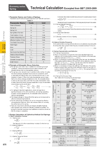
11 checked in Figure 2. When the cycle characteristic value is large, 3.3.2 Spring End Structure Type
See Table 2 for the spring end structure type.
that is, the stress (change) amplitude is small, the allowable stress Table 2
is taken as the large value; and when the cycle characteristic value Shape Code Sketch End Structure Type
Springs / Posts γ= τmin = F max or γ = σmax = T max = φ max EEEEEE(1) YI Both end coils tightened
is small, that is, the stress (change) amplitude is large, the allowable
stress is taken as the small value.
and grinding
T min
φ min
F min
σmin
nZ ≥ 2
τmax
c) For springs in important applications, where damage has a
but not grinding
significant impact on the entire machinery, and springs operating Cold Coil Compression Spring YII Both end coils tightened
at higher or lower temperatures, the allowable stress should be nZ ≥ 2
reduced appropriately. Both end coils not
d) The fatigue strength or fatigue life of the spring can be improved by YIII tightened
effective shot peening treatment. nZ < 2
e) For the coil springs, the fatigue life can be increased by effective
strong pressure treatment, which has obvious effect on improving RYI Both end coils tightened
and grinding
the performance of the spring. nZ ≥ 1.5
f) There are many factors affecting the fatigue strength of springs
under dynamic load, which are difficult to estimate accurately. For Both end coils tightened
springs for important purposes, test verification should be carried out RYII but not grinding
after the design is completed. Hot Coil Compression Spring nZ ≥ 1.5
3 Design Calculation of Cylindrical Helical Coil Springs RYIII Both end coils flattened,
tightened and grinding
3.1 Basic Calculation Formula nZ ≥ 1.5
3.1.1 Spring Load: Both end coils flattened,
F= Gd 4 f EEEEEEEEEEEEEEEEEEEEE (2) RYIV tightened but not grinding
8D 3 n
nZ ≥ 1.5
See Appendix A for the material shear modulus G in the formula.
3.1.2 Spring Deflection: Table 3 Shear Modulus of Elasticity(G)
8D 3 nF G Value N/mm 2
f = Gd 4 EEEEEEEEEEEEEEEEEEEEE (3) Material (kgf/mm 2 ) Symbol
3.1.3 Spring Stiffness: Spring Steel 78 × 10 3 {8 × 10 3 } SUP6, 7, 9, 9A, 10, 11A, 12, 13
F Gd 4 Hard Steel Wire 78 × 10 3 {8 × 10 3 } SW-B,SW-C
F' = f = 8D 3 n EEEEEEEEEEEEEEEEEEEE (4) Piano Wire 78 × 10 3 {8 × 10 3 } SWP
SWO, SWO-V, SWOC-V,
3.1.4 Spring Tangential Stress: Oil Tempered Steel Wire 78 × 10 3 {8 × 10 3 } SWOSC-V, SWOSM, SWOSC-B
πd 3 EEEEEEEEEEEEEEEEEEEEE (5)
τ =K 8DF SUS 302 SUS 302
SUS 304
SUS 304
or Stainless SUS 304N1 69 × 10 3 {7 × 10 3 } SUS 304N1
Gdf
τ=K πD 2 n EEEEEEEEEEEEEEEEEEEEE (6) Steel Wire
SUS 316
SUS 316
875 SUS 631 J1 74 × 10 3 {7.5 × 10 3 } SUS 631 J1