
Page 881 - MISUMI Thailand Economy Series
P. 881
Economy series Economy series
Spring Technical Calculation Excerpted from GB/T 23935-2009 Technical Calculation Excerpted from GB/T 23935-2009 Spring
4.1.7 Effective Number of Coils of Spring
3.3.3 Spring Material Diameter n= Gd 4 f EEEEEEEEEEEEEEEEEEE (25)
The spring material diameter d is calculated by Formula (8) and should 8D 3 (F─F0)
be generally complied with GB/T 1358-2009 series. 4.1.8 Deflection Energy
3.3.4 Spring Diameter 1
a) Spring Mean Diameter: U = (F+F0) f EEEEEEEEEEEEEEEEEEEEE (26)
2
D = D1 + D2 EEEEEEEEEEEEEEEEEEEEEE (14) 4.2 Spring Characteristics and Deflection
2
4.2.1 Spring Characteristics
b) Spring I.D.:
D1 = D ─ d EEEEEEEEEEEEEEEEEEEEEEE(15) The design calculation is the same as that of cylindrical spiral compression springs.
4.2.2 Test Load
c) Spring O.D.: The design calculation is the same as that of cylindrical spiral compression springs.
D2 = D + d EEEEEEEEEEEEEEEEEEEEEEE(16) Coil Springs
4.2.3 Initial Tension
The spring mean diameter D should be generally complied with the GB/T 1358- The close coil tension spring made of materials that do not need
2009 series, and the deviation value can be selected according to GB/T 1239.2- quenching and annealing forms an axial pressure between the coils,
2009 and GB/T 23934-2015. In order to ensure sufficient installation space, the which is called the initial tension F0. When the applied load exceeds the P.865
increase in diameter of the spring under load should be considered. initial tension, the spring begins to deform. After coiling and forming,
a) When both ends of the spring are fixed, from the free height to tightening, the springs that need to be quenched and annealed have no initial tension.
increase in the mean diameter is calculated according to the approximate formula (17): The initial tension is calculated according to Formula (27): Springs Tension
Δ D =0.05 t 2 ─ d 2 EEEEEEEEEEEEEEEEEE (17) F0 = πd 3 τ0 EEEEEEEEEEEEEEEEEEEEE (27)
D
b) When the two end faces and the supporting seat can rotate freely and the friction is small, 8D P.875
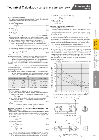
the increase in the mean diameter is calculated according to the approximate formula (18): In the formula, τ 0 is the initial tangential stress. For the steel spring, its value
can also be selected in the shaded part of Figure 1 according to the winding
Δ D =0.1 t 2 ─ 0.8td ─ 0.2d 2 EEEEEEEEEEEEEEE(18) ratio C. As the spring generally needs stress relief annealing treatment, the
D
3.3.5 Number of Coils of Spring initial tension of the spring will decrease after treatment. In order to facilitate Tension Springs Posts for
3.3.5.1 The effective number of coils of spring is calculated by Formula (10) and should manufacturing, it is recommended to take the lower limit value.
be generally complied with the provisions of GB/T 1358-2009. In order to avoid At the same time, its value can also be calculated by referring to
excessive additional forces due to load eccentricity, and to ensure stable stiffness, empirical formula (28): P.881
there are generally no less than 3 coils and at least no less than 2 coils. τ0 = G EEEEEEEEEEEEEEEEEEEEEE (28)
3.3.5.2 The supporting coil n z is related to the structural type of the end coil, and the value of n z is shown in Table 2. 100C
3.3.5.3 Total Number of Coils 220
n 1 =n +n z EEEEEEEEEEEEEEEEEEEEEEE(19) 200 Disc Springs Torsion Springs/
The mantissa should be 1/4, 1/2, 3/4 or the whole coil, and 1/2 coil is recommended.
3.3.6 Spring Free Height 180 P.884
3.3.6.1 The free height H 0 is affected by the end structure, so it is difficult to calculate 160 11
the exact value and its approximate value is calculated according to the formula 140
listed in Table 3, as recommended to follow the provisions of GB/T 1358-2009.
Table 4 Initial Tangential Stress τ0 /MPa 120
Total Number of Coils n 1 Free Height H 0 Pitch t End Structure Type 100
n+1.5 nt+d (H 0-d)/n 80 Springs / Posts
n+2 nt+1.5d (H 0-1.5d)/n Both end coils
grinding
n+2.5 nt+2d (H 0- 2d)/n 60
n+2 nt+3d (H 0-3d)/n Both end coils 40
n+2.5 nt+3.5d (H 0-3.5 d)/n not grinding
20
3.3.6.2 Solid Height
The solid height of the spring is not specified in principle. 0 3 4 5 6 7 8 9 10 11 12 13 14 15 16
a) For a spring with 3/4 coil of end face grinding, when it is necessary to C=D/d
specify the solid height, it is calculated according to Formula (20): Figure 1 Relationship Diagram Between Winding Ratio and Initial Tangential Stress
H b ≤ n 1d max EEEEEEEEEEEEEEEEEEEEE(20)
4.2.4 Spring Working Drawing (See Figure 2) (Fs)
b) For a spring without grinding at both ends, when it is necessary to F1 F2
specify the solid height, it is calculated according to Formula (21): F0
H b ≤(n 1+1.5)d max EEEEEEEEEEEEEEEEEE (21) H1
Where: H2
d max ---Maximum Material Diameter (Material Diameter + (Hs)
Maximum Limit Deviation), in millimeter (mm). (h2)
4 Design Calculation of Cylindrical Helical Tension Spring
4.1 Basic Calculation Formula
When there is no initial tension, the basic calculation formula of the tension spring is d
the same as that of coil springs, calculated according to Formula (2) to Formula (11). h1 H0
When there is initial tension, the basic calculation of the tension spring is calculated according to Formula (22) to Formula (26). a) With Initial Tension
4.1.1 Spring Load F2 (Fs)
F = Gd 4 f+F0 EEEEEEEEEEEEEEEEEEEE(22) F1
8D 3 n
H1
4.1.2 Spring Deflection H2
Gd 4 (F─F0) EEEEEEEEEEEEEEEEEEE(23)
f = 8D 3 n (Hs) (h2)
4.1.3 Spring Stiffness
Gd 4
F' = F ─ F0 = 8D 3 n EEEEEEEEEEEEEEEEEE (24)
f
d
4.1.4 The spring Torsional Stress is calculated according to Formula (5) or Formula (6). h1 H0
4.1.5 The spring material diameter is calculated according to Formula (8).
4.1.6 The spring mean diameter is calculated according to Formula (9). b) Without Initial Tension
Figure 2 Tension Spring Working Drawing 876